NOTE: For the circuit ID sub-option of a standalone switch, the module field is always zero.
Circuit ID sub-option format:
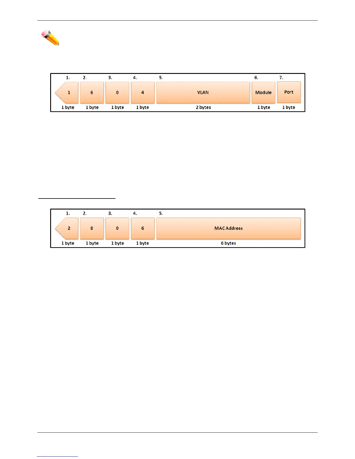
Figure 9-2 Circuit ID Sub-option Format
1 Sub-option type
2 Length
3 Circuit ID type
4 Length
5 VLAN: The incoming VLAN ID of DHCP client packet.
6 Module: For a standalone switch, the Module is always 0; for a stackable switch, the Module is the Unit ID.
7 Port: The incoming port number of the DHCP client packet, the port number starts from 1.
Remote ID sub-option format:
Figure 9-3 Remote ID Sub-option Format
1 Sub-option type
2 Length
3 Remote ID type
4 Length
5 MAC address: The Switch’s system MAC address.
DHCP Relay Interface Settings
Users can set up a server, by IP address, for relaying DHCP information to the Switch. The user may enter a
previously configured IP interface on the Switch that will be connected directly to the DHCP server using this
window. Properly configured settings will be displayed in the DHCP Relay Interface Table at the bottom of the
window, once the user clicks the Apply button. The user may add up to four server IPs per IP interface on the
Switch. Entries may be deleted by clicking the corresponding Delete button.
To view this window, click Network Application > DHCP > DHCP Relay > DHCP Relay Interface Settings, as
shown below:

 Loading...