xStack® DES-3528/DES-3552 Series Layer 2 Managed Stackable Fast Ethernet Switch Web UI Reference Guide
33
NOTE: If there is a Box ID conflict when the stack is in the discovery phase, the device will enter
a special standalone topology mode. Users can only get device information, configure
Box IDs, save and reboot. All stacking ports will be disabled and an error message will be
produced on the local console port of each device in the stack. Users must reconfigure
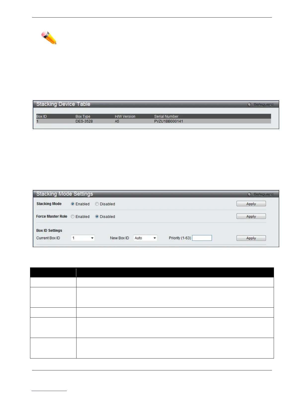
Stacking Device Table
This window is used to display the current devices in the Switch Stack.
To view this window, click System Configuration > Stacking > Stacking Device Table, as shown below:
Figure 2-28 Stacking Device Table window
Stacking Mode Settings
To begin the stacking process, users must first enable this device for stacking by using the Stacking Mode Settings
window.
To view this window, click System Configuration > Stacking > Stacking Mode Settings, as shown below:
Figure 2-29 Stacking Mode Settings window
The fields that can be configured or viewed are described below:
Parameter Description
Stacking Mode
Click the radio buttons to enable or disable the stacking function.
Force Master Role
Use the radio buttons to enable or disable the function. It is used to ensure the master role is
unchanged when adding a new device to the current stacking topology. If the Enabled radio
button is selected, the master’s priority will become zero after the stacking has stabilized.
Current Box ID
The Box ID of the Switch in the stack to be configured.
New Box ID
The new box ID of the selected switch in the stack that was selected in the Current Box ID
field. The user may choose any number between 1 and 8 to identify the Switch in the switch
stack. Auto will automatically assign a box number to the Switch in the switch stack.
Priority (1-63)
Displays the priority ID of the Switch. The lower the number, the higher the priority. The box
(switch) with the lowest priority number in the stack is the Primary Master switch. The
Primary Master switch will be used to configure applications of the switch stack.
Click the Apply button to accept the changes made.

 Loading...