xStack® DES-3528/DES-3552 Series Layer 2 Managed Stackable Fast Ethernet Switch Web UI Reference Guide
341
The fields that can be configured are described below:
Parameter Description
IPv4 Address / IPv6
Address
The IP address of the destination station.
TTL (1-60)
The time to live value of the trace route request. This is the maximum number of routers
that a trace route packet can pass. The trace route option will cross while seeking the
network path between two devices.
The range for the TTL is 1 to 60 hops.
Port (30000-64900) The port number. The value range is from 30000 to 64900.
Timeout (1-65535)
Defines the timeout period while waiting for a response from the remote device. A value
of 1 to 65535 seconds can be specified. The default is 5 seconds.
Probe (1-9) The number of probing. The range is from 1 to 9. If unspecified, the default value is 1.
Click the Start button to initiate the Trace Route.
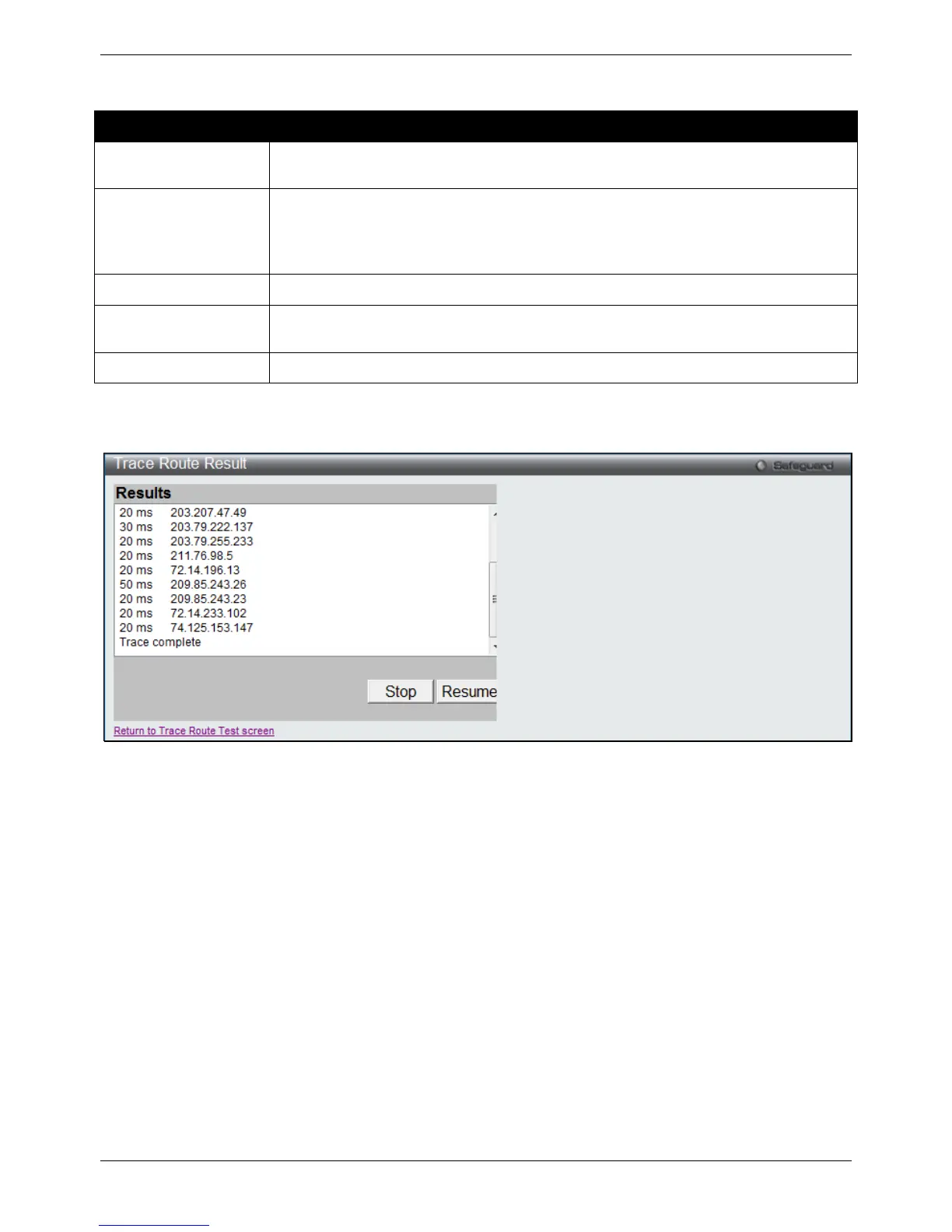
After clicking the Start button, the following page will appear:
Figure 11-26 Trace Route Result window
Click the Stop button to halt the Trace Route.
Click the Resume button to resume the Trace Route.
Peripheral
Device Status
This window displays power and fan status of the Switch.
To view this window, click Monitoring > Peripheral > Device Status, as shown below:

 Loading...