4. Please make sure the front-end device has soundly earthed.
Improper grounding may result in chip damage.
3.7.1 Alarm Input and Output Details
Important
Please refer to the specifications for the alarm input and output channel amount. Do not merely
count the alarm input and out channel amount according to the ports on the rear panel.
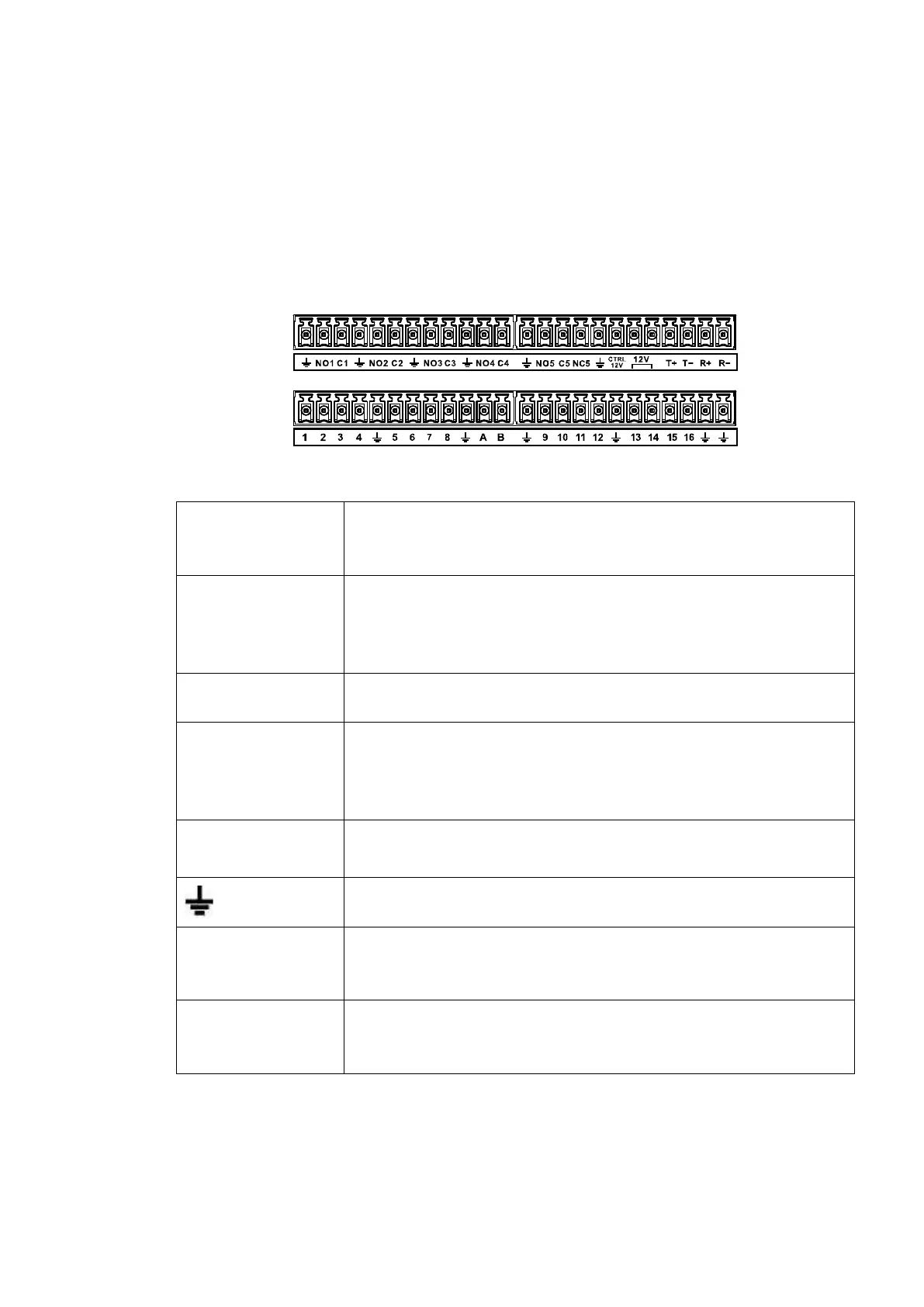
Figure 3-1
1,2,3,4,5,6,
7,8,9,10,11,
12,13,14,15,16
ALARM 1 to ALARM 16. The alarm becomes active in low voltage.
NO1 C1,
NO2 C2,
NO3 C3,
NO4 C4,
There are four groups of normal open activation output (on/off
button)
There is one group of normal open activation output (on/off button)
Control power output of the 6
th
alarm output channel. Voltage
current: 500mA.
When there is an alarm output, close the power output.
When the alarm is cancelled, open the power output.
Rated current.
Voltage current: 500mA.
485 communication port. They are used to control devices such as
decoder. 120Ω should be parallel connected between A, B lines if
there are too many PTZ decoders.
They are four-wire full-duplex RS485 port
T+ T-: output wire
R+ R-: input wire
3.7.2 Alarm Input Port
Please refer to the following sheet for more information.
Grounding alarm inputs. Normal open or Normal close type)
 Loading...