1.4 <DTA109A51> DIII-NET Expander Adaptor 297
Adaptor
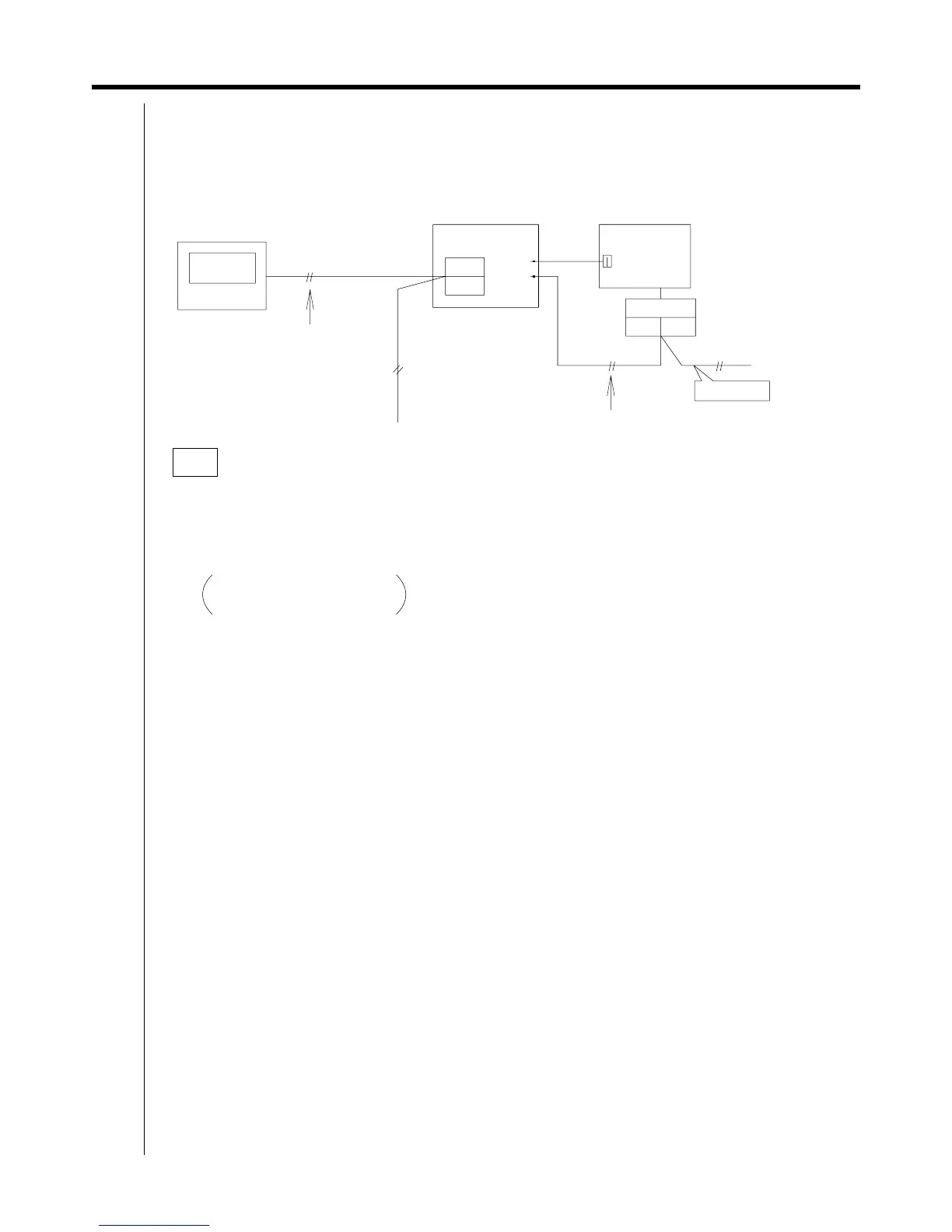
1.4.4 Electric Wiring Work
C : 1P013360
Notes
Total length : 2000m
Max. length : 1000m
Max. number of branches : 16
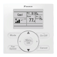
• At least one outdoor unit and one optional controller for centralized control are required for every main bus and
branch bus.
• Up to 8 adaptors can be connected in one system.
• Do not locate adaptors downstream of other adaptors (i.e. : on a branch bus).
• If not used with a central control device, the expander adaptor cannot be used with the wiring adaptor for
electrical appendices (KRP2A) or the schedule timer (DST301B51).
• The external control adaptor for outdoor units controls group cooling and demand for each adaptor.
(Anything beyond the expansion control falls outside the control domain.)
• Do not turn the system ON/OFF rapidly from the optional controller for centralized control. This can cause
temporary erroneous displays.
• Sequential starts is controlled by each expander adaptor.
(Transmission wiring specifications)
• 0.75 ~ 1.25mm
2
sheathed wire (2 wire).
(Transmission wiring length)
• Observe the following limits on transmission wires.The limits apply to each adaptor.If you exceed the limits,
it may cause malfunction.
(1) Connect the wire from the adaptor to the adaptor power connector on the outdoor unit's PC board.
(For connector Nos.,see the electric wiring diagrams for the indoor and function units.)
(2) Connect transmission wires between outdoor units (Outdoor-Outdoor terminal board).
(3) Wire transmission wires to terminal boards as shown below.
~
F2
F1
F1 F2
Branch bus
Non-polarity
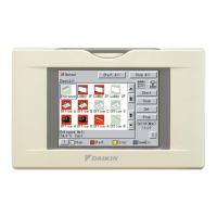
Central remote controller
Outdoor-Outdoor
~
Main bus
Outdoor unit
PC board
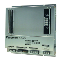
adaptor


 To Next Page