1.5 Dio Unit (DEC102A51) 307
Adaptor
1.5.4 Electric Wiring Work and Initial Setting
1. Electric Wiring Work
2. Initial setting
z DEC102A51 Switch Settings
Note:
1. All are set to "OFF" upon shipment from factory.
2. *1 If operating feedback input is not detected within 10 seconds after 1 operation input is received, it results in start/
stop failure.
Name Operation OFF ON
SS1 Output switching Switching control output
Always output
"1"
Always output
“2”
DS2 Abnormal input detection Open/Close
Failure detection
Open: Close (Normal)
→
Open (Abnormal)
Close:
Open (Normal)
→
Close (Abnormal)
Open Close
DS3 Buzzer output ON/OFF
ON/OFF switching of buzzer output of
buzzer unit upon detection of failure.
ON OFF
DS4-1 Instantaneous automatic recovery
Recover control output after power failure
to status before the power failure.
No Yes
DS4-2 Transmission failure
Shut off control output upon detecting
transfer failure.
Yes No
DS4-3 Later operation priority Allowing start/stop control from facility. Yes No
DS4-4 Start/stop failure Detecting start/stop failure. (*1) No Yes
DS5 Abnormal output shutoff/retain
Shut off control output upon detecting
failure.
Yes No
DS6-1 Startup failure
Masking time after detecting operation
input.
10 seconds 30 seconds
DS6-2 Failure detection Operation upon recovery from failure.
Automatic
reset
Retained
DS6-3 Monitor input Detecting failure under halting status. Yes No
DS6-4 Forced termination Ignoring forced stop signal. No Yes
176325
ON
48
1763254
1324
8
ON
ON
DS6
Ins.
SS1
Con.
Contactor
DS5 DS4
RS1 Low
DS1 High
Group No. Set
0
DS2
DS3
D4D2 D3D1CD
Aiarm
Monitor
(RED)
Operation
Monitor
(GRN)
H11P H12P
2
H3P
1
H10P
3
H9P
4
INPUT
H2P H4PH1P
M4
A1
M3
A3CA
M2
A2
M1
A4
CM
L
N
F1
F2
X4M
TNc4
TNa2
AC200V
~240V
TNb3
TNc1
X1M
X3M
LED10
RED
TNc3
TNa1 TNb4TNb2
HAP
HAP
GRN
TNc2
TP1
H10P
X2M
TNa4TNa3TNb1
X2A
X1A
YE
RED
1
234
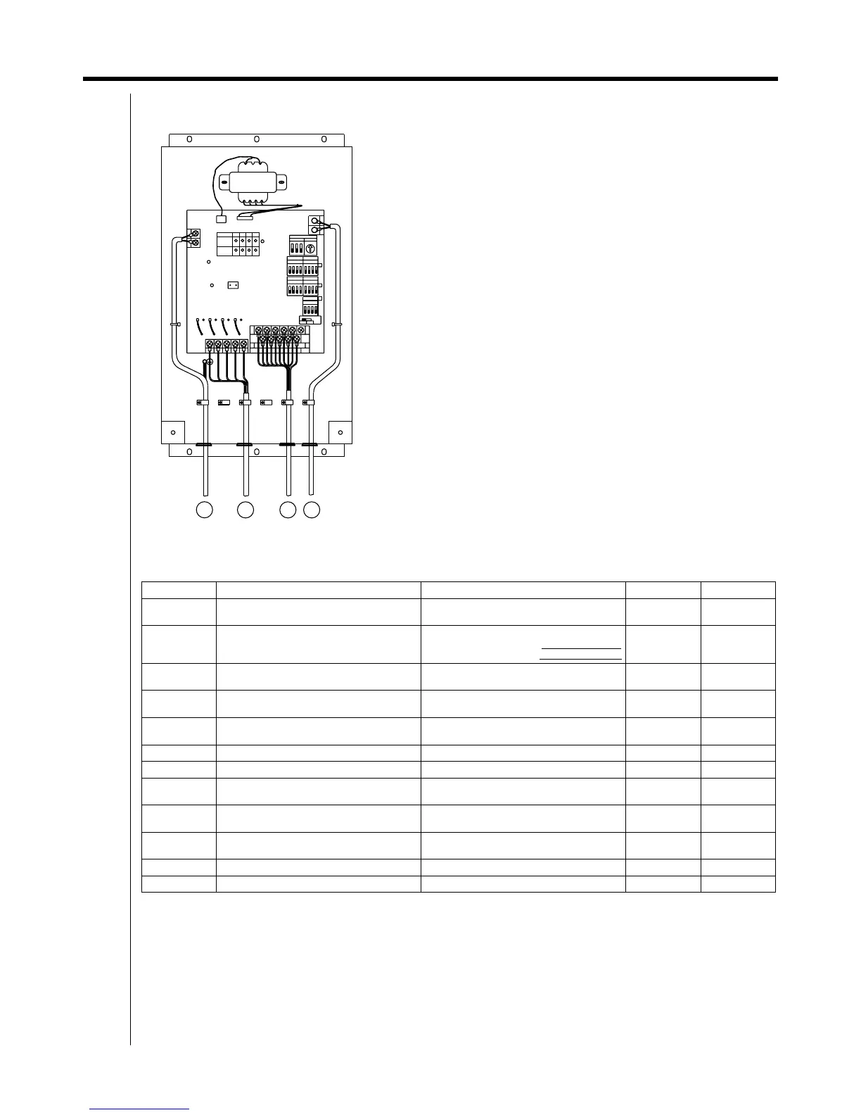
No simultaneous clamping is allowed for high-voltage wiring
<power supply wiring (L/N), earth wiring, relay output wiring
(CD, D1 to 4)>, low-voltage wiring <communication wiring (F1/F2),
operation input wiring (CM, M1 to 4) and abnormal input wiring
(CA, A1 to 4)> since malfunctioning may result.
Also, in case where the wirings described above are routed in parallel,
be sure to connect the wirings at least 50mm apart from the other.
To 1~200-240V and earth
To facility equipment
To facility equipment
To terminals F1, F2 of the centralized control equipment or terminals
F1, F2 of other equipment
(outdoor unit, DEC101A51, 102A51)