A A B B
C C
-TB1.1
DC+ DC-
L1 L2 L3
PE
-TB1.2
DC+ DC-
L1 L2 L3
PE
-TB2.1
DC+ DC-
U V W
PE
-TB2.2
DC+ DC-
U V W
PE
+MAXX
1
2
-FC2.1
1
2
-FC2.2
1
2
-FC2.3
1
2
-FC2.4
DC+
DC-
DC+
DC-
1
2
-FC3.1
1
2
-FC3.2
1
2
-FC3.3
1
2
-FC3.4
+MAC2
+MAU2
+MAU1
+MAU2
U1
U2
W2V2
V1 W1 V1
V2
W1
+MAU1
+MAU2
-TB2.1
U/T1 V/T2 W/T3
PE
W1V1U1
21
PE
3~
M
Θ
+MAC2
+MAU2
+MAU1
+MAU2
U1
U2
W2
+MAU1
+MAU2
-TB2.1
U/T1 V/T2 W/T3
PE
PE
DC+
DC-
FAN1+
FAN1-
FAN2+
FAN2-
1L2
1L1
1L3
2L2
2L1
2L3
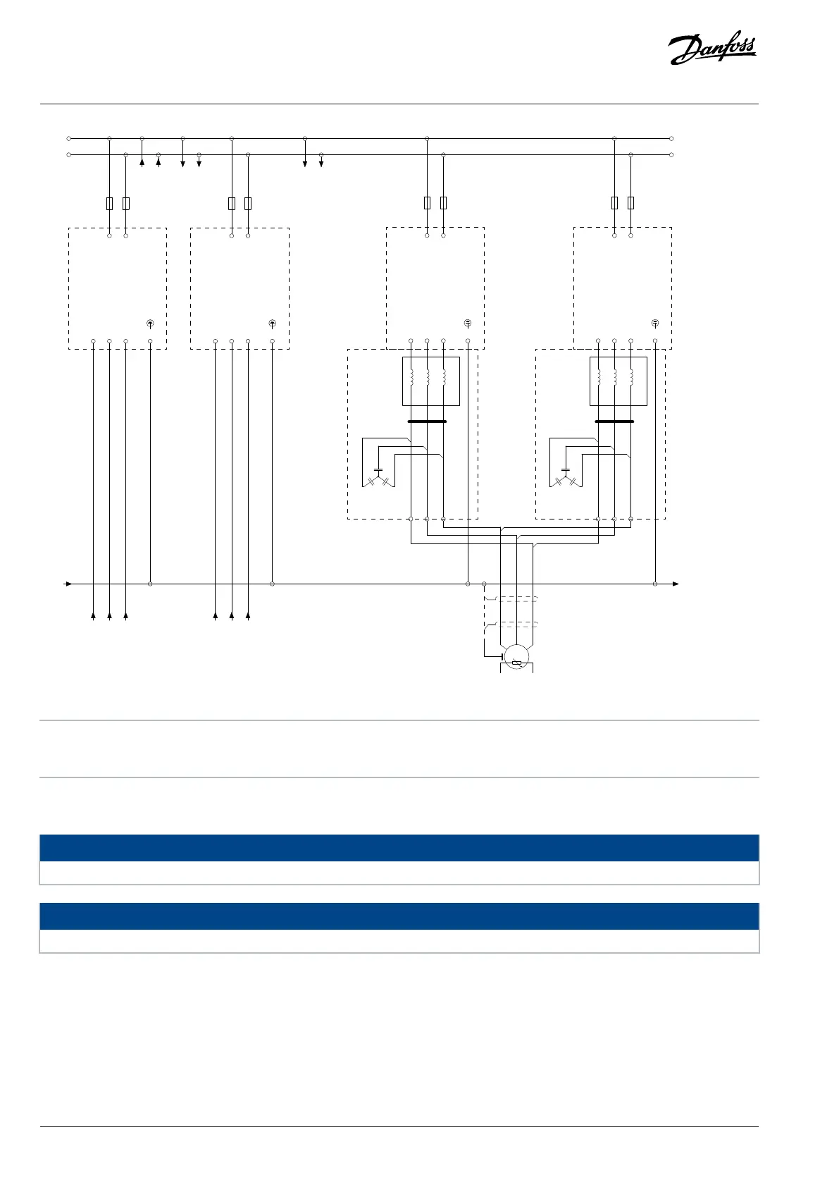
e30bj481.11
Figure 78: Wiring Diagram, 2 x AE11+2 x IE11, 1260–1710 A (continued)
A Power unit of the AFE module B Power unit of the inverter module
C Integration unit
9.3.6 Pre-charging Control Wiring Diagram, AE10, AE11, IE10, IE11
NOTICE
This is a generic presentation of the system. Refer primarily to the wiring diagrams delivered with the product.
NOTICE
The products with frame designations FE9 and FE10 do not have a pre-charging control circuit.
104 | Danfoss Drives Oy © 2024.09 AJ389643274589en-000101 / 172F6409A
Design Guide | iC7-Automation Air-cooled Enclosed Drives Specifications