Design Guide | iC7-Automation Air-cooled Enclosed Drives Specifications
l Multicore cables installed in cable ducts.
¢ If cable ducts are not used, keep sufficient spacing between the cables.
¢ Do not stack or bundle the cables without proper spacing for longer than 600 mm (24 in).
In other conditions, refer to the local safety regulations, the input voltage, and the load current of the drive.
It is possible to use M12 cable lugs for the mains cables.
NOTICE
Use symmetrical cabling with system modules connected in parallel. Each module must have the same number of cables with an
equal cross-section.
The cable size tables for the enclosed drives can be found with these links.
l
9.5.2 Mains Cable Size Recommendations, 380–500 V
l 9.5.3 Motor Cable Size Recommendations, 380–500 V
l 9.5.4 Mains Cable Size Recommendations, UL 480 V
l 9.5.5 Motor Cable Size Recommendations, UL 480 V
l 9.5.6 Brake Cable Size Recommendations
l 9.5.7 Brake Cable Size Recommendations, UL
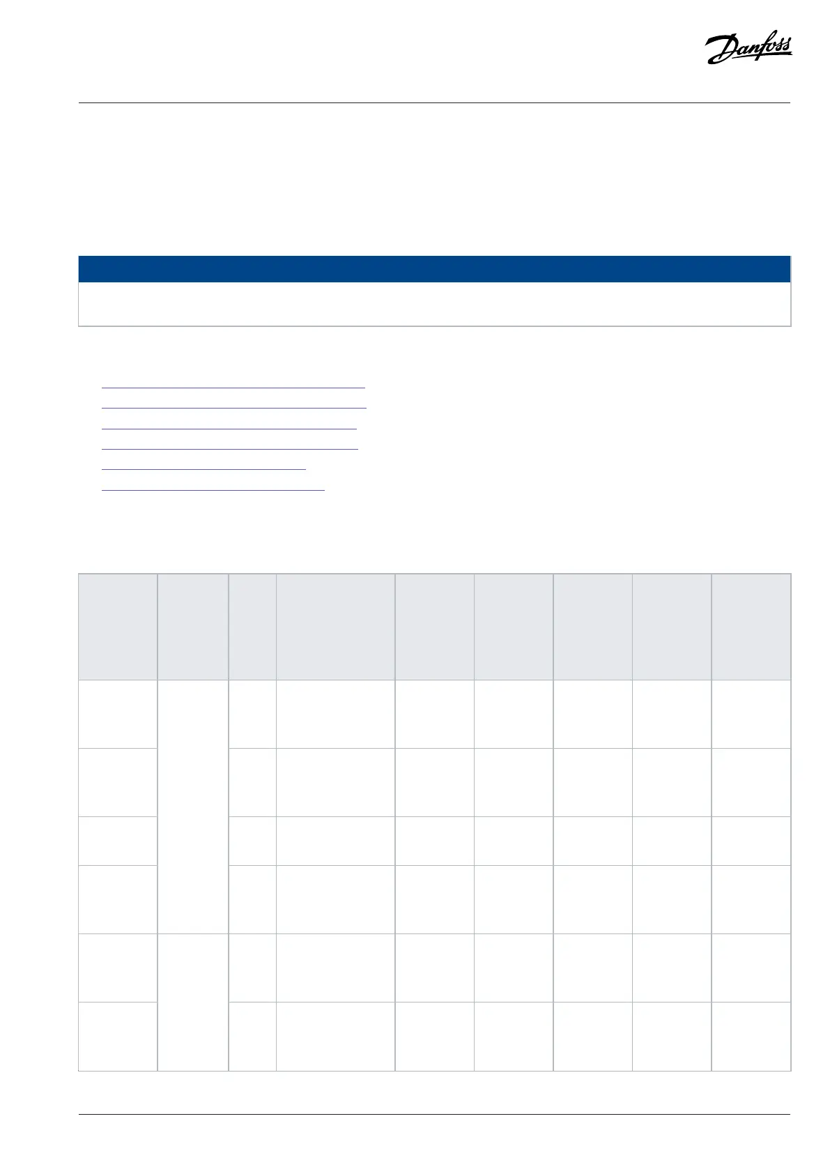
9.5.2 Mains Cable Size Recommendations, 380–500 V
Table 40: Mains Cable Size Recommendations, 380–500 V
Model
code
Frame I
N
[A]
Cable [mm
2
]
Maximum
cable size
[mm
2
]
Maximum
number
of mains
cables
(1)
Hole size of
the mains
terminal
[mm]
Number of
grounding
holes on PE
busbar
Hole size
of the
grounding
terminal
[mm]
iC7-60EA3N
05-206A
206 Cu 1 x (3x70+35)
Al 1 x (3x120+41
Cu)
95 Cu/Al 2 Ø10.5 2 Ø10.5
iC7-60EA3N
05-245A
245 Cu 1 x (3x95+50)
Al 1 x (3x150+41
Cu)
95 Cu/Al 2 Ø10.5 2 Ø10.5
iC7-60EA3N
05-302A
302 Cu 1 x (3x120+70)
Al 2 x (3x95+29 Cu)
95 Cu/Al 2 Ø10.5 2 Ø10.5
iC7-60EA3N
05-385A
FE9
(2)
385 Cu 2 x (3x95+50)
Al 2 x (3x120+41
Cu)
95 Cu/Al 2 Ø10.5 2 Ø10.5
iC7-60EA3N
05-480A
480 Cu 2 x (3x120+70)
Al 2 x (2x185+57
Cu)
150 Cu/120
Al
3 Ø13.5 4 Ø10.5
iC7-60EA3N
05-588A
FE10
(2)
588 Cu 2 x (3x150+70)
Al 2 x (3x240+41
Cu)
150 Cu/120
Al
3 Ø13.5 4 Ø10.5
Danfoss Drives Oy © 2024.09 AJ389643274589en-000101 / 172F6409A | 109