7 Control and Option Installation
7.1 General Information of the Control Compartment
The enclosed drive has a door-mounted control compartment for the control terminals, separated from the cabinet section. The control
compartment is accessed through a separate door on the cabinet door.
Make sure that the control cables are long enough. This prevents tight bends in the cables between the control compartment and the
frame of the drive and ensures that the control compartment can be fully opened during module maintenance.
The 2 first I/O option boards are wired into the terminal blocks on the control compartment, and the next ones directly into the option
board terminals. The wiring of the boards:
l I/O and Relay Option OC7C1 as standard I/O: on the terminal block on the control compartment
l Relay Option OC7R0: on the terminal block on the control compartment
l General Purpose I/O OC7C0: on the terminal block on the control compartment
l I/O and Relay Option OC7C1 as an option: on the option board
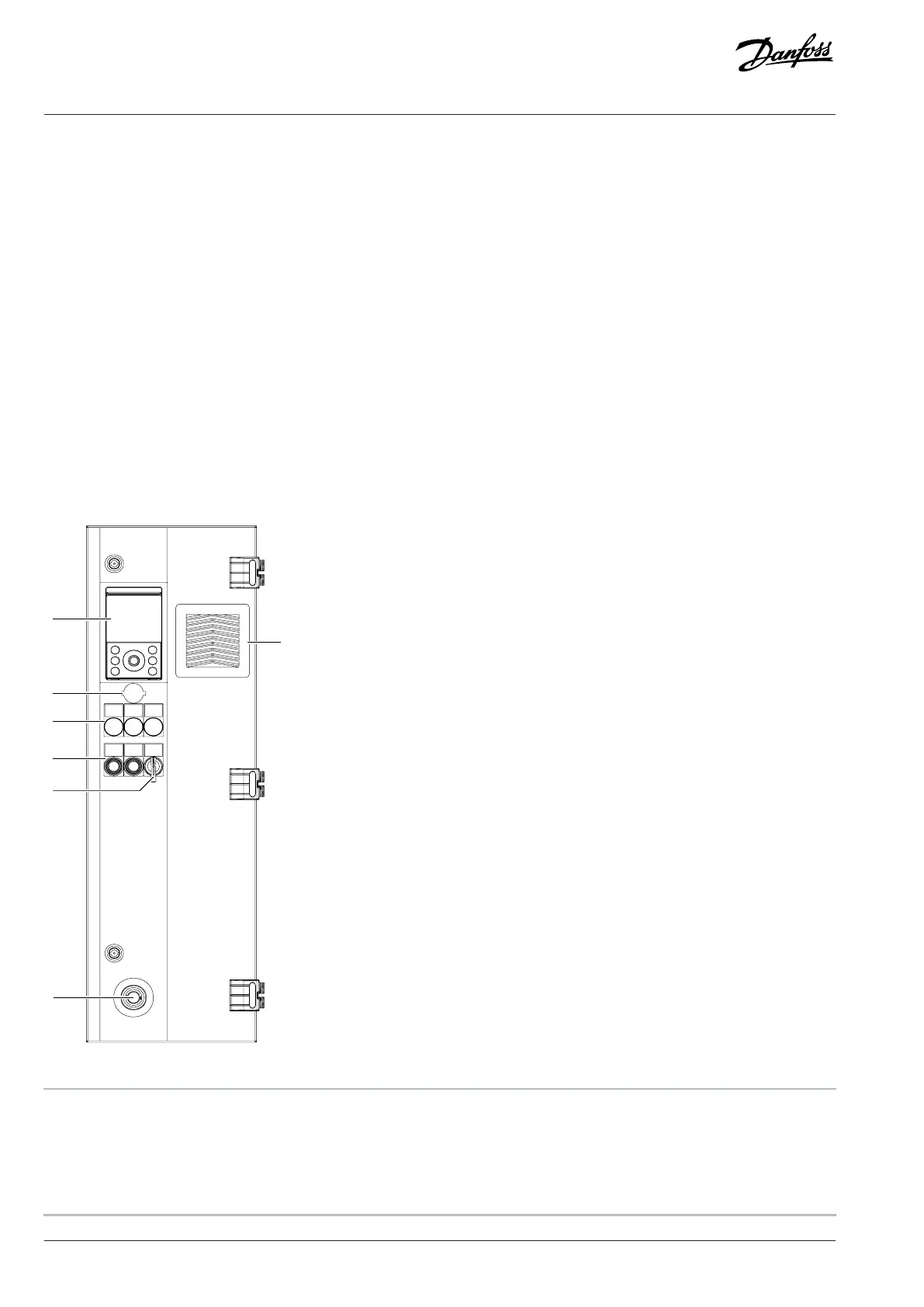
7.2 Control Compartment Door Elements
Figure 30: Control Compartment Door Elements, FE9, FE10
1 Control panel, -PGA 2 Ethernet port, RJ45
3 Run, ready, and fault lights (+IICD), -PF3, -PF4, -PF5 4 Mains contactor push button Open/Close, -SF7.1, -SF7.2
5 Mains contactor Local/Remote switch, -SFB 6 Emergency stop button (+ILSS), -SFG
7 Fan and filter cover and optional IP54 filter (+IP54)
48 | Danfoss Drives Oy © 2024.09 AJ389643274589en-000101 / 172F6409A
Design Guide | iC7-Automation Air-cooled Enclosed Drives Control and Option Installation