Design Guide | iC7-Automation Air-cooled Enclosed Drives Control and Option Installation
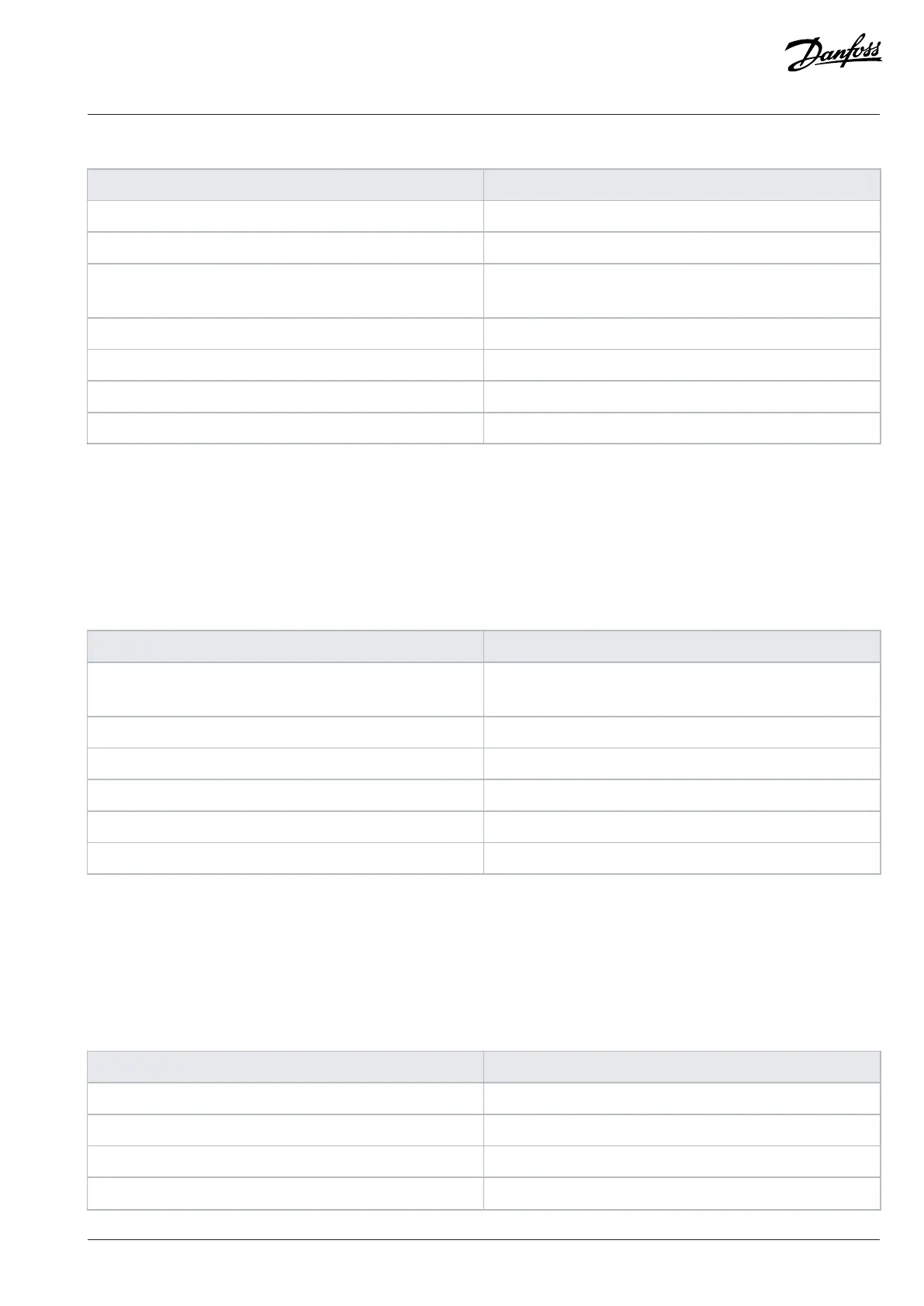
Table 23: Digital Inputs Logic Levels and Other Requirements
Parameter Value
Recommended Operation Voltage 0...24 V +20%/-10%
Overvoltage Limit 33 V
Logic Level 0 = V
TL
≤ 5 V
1 = V
TH
≥ 15 V
Input Load 7.5 mA constant current and 10 kΩ resistive load
Reaction Time < 5 µs
Maximum Frequency 100 kHz
Electrical fast transient (EFT) 2 kV
7.7.4 Digital Outputs
The I/O and Relay Option has 2 digital outputs. The digital outputs are the push-pull type. The digital outputs can also be used as the
open collector type.
The digital outputs are short-circuit protected.
Table 24: Digital Output Voltage and Current
Parameter Value
Output Voltage 0 = max 2 V
1 = min 20 V
Rated Current ±50 mA
Overcurrent Limit ±80 mA
Maximum voltage when used as open collector output 48 V
Maximum Frequency 100 kHz
Electrical fast transient (EFT) 2 kV
1) Control unit power supply 24 V +20%/-10% and I
load
max 50 mA
7.7.5 Relay Outputs
The I/O and Relay Option has 3 relay outputs. Relay 1 and Relay 2 have NO and NC contacts [1 form C (CO)]. Relay 3 has only an NO
contact [1 form A (NO)]. The relay output interface is reinforced for system voltages ≤ 300 V. The lifetime for relays is 100.000 cycles.
Table 25: Relay Output Values
Parameter Value
Rated Voltage 250 V AC
Max. Switching Voltage 400 V AC
Rated Current 8 A
Breaking Capacity Max 2000 VA
Danfoss Drives Oy © 2024.09 AJ389643274589en-000101 / 172F6409A | 61