9.3 Wiring Diagrams
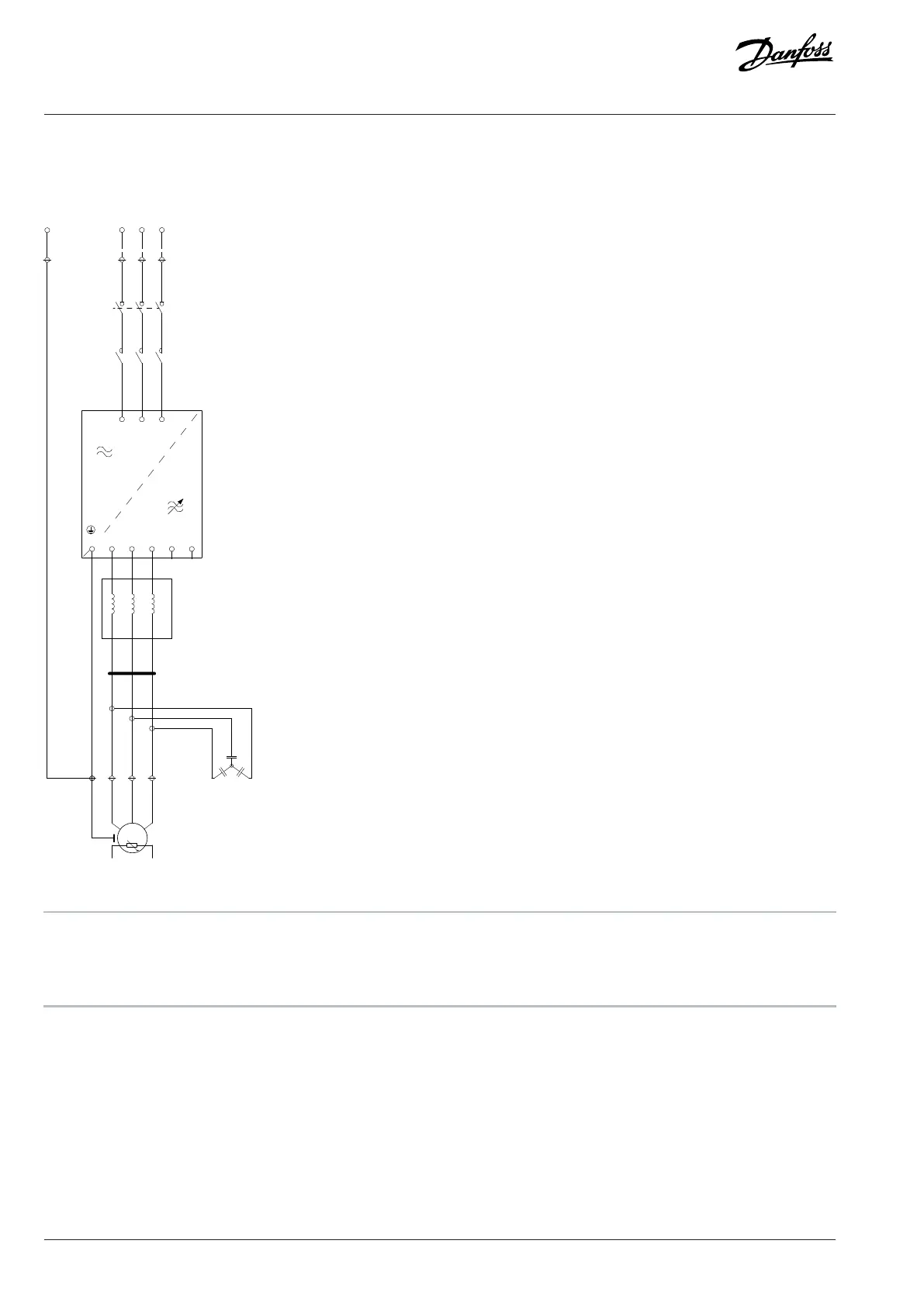
9.3.1 Wiring Diagram, FE9, FE10
D
C
U V W
U’ V’ W’
A
B
E
PE
1
2
4
3
6
5
L1 L2 L3
1
2
3
4
5
6
DC+ DC-U V WPE
L1 L2 L3
U V W
W1V1U1
21
PE
3~
M
Θ
U
V
W
PE
L1 L2 L3
PE
e30bj436.11
Figure 70: Wiring Diagram, FE9, FE10
A Switch disconnector +GAMS B Contactor +GACO
C dU/dt Filter choke +MADU D Common-mode Filter +MACM
E dU/dt Filter capacitor +MADU
96 | Danfoss Drives Oy © 2024.09 AJ389643274589en-000101 / 172F6409A
Design Guide | iC7-Automation Air-cooled Enclosed Drives Specifications