11 Motor terminals (behind PE busbar, Top-entry option) 12 Mains terminals (Top-entry option)
13 Brake terminals (Top-entry option) 14 Control cable grommet, top
15 IP54 grommet for mains and motor cables (Top-entry
option)
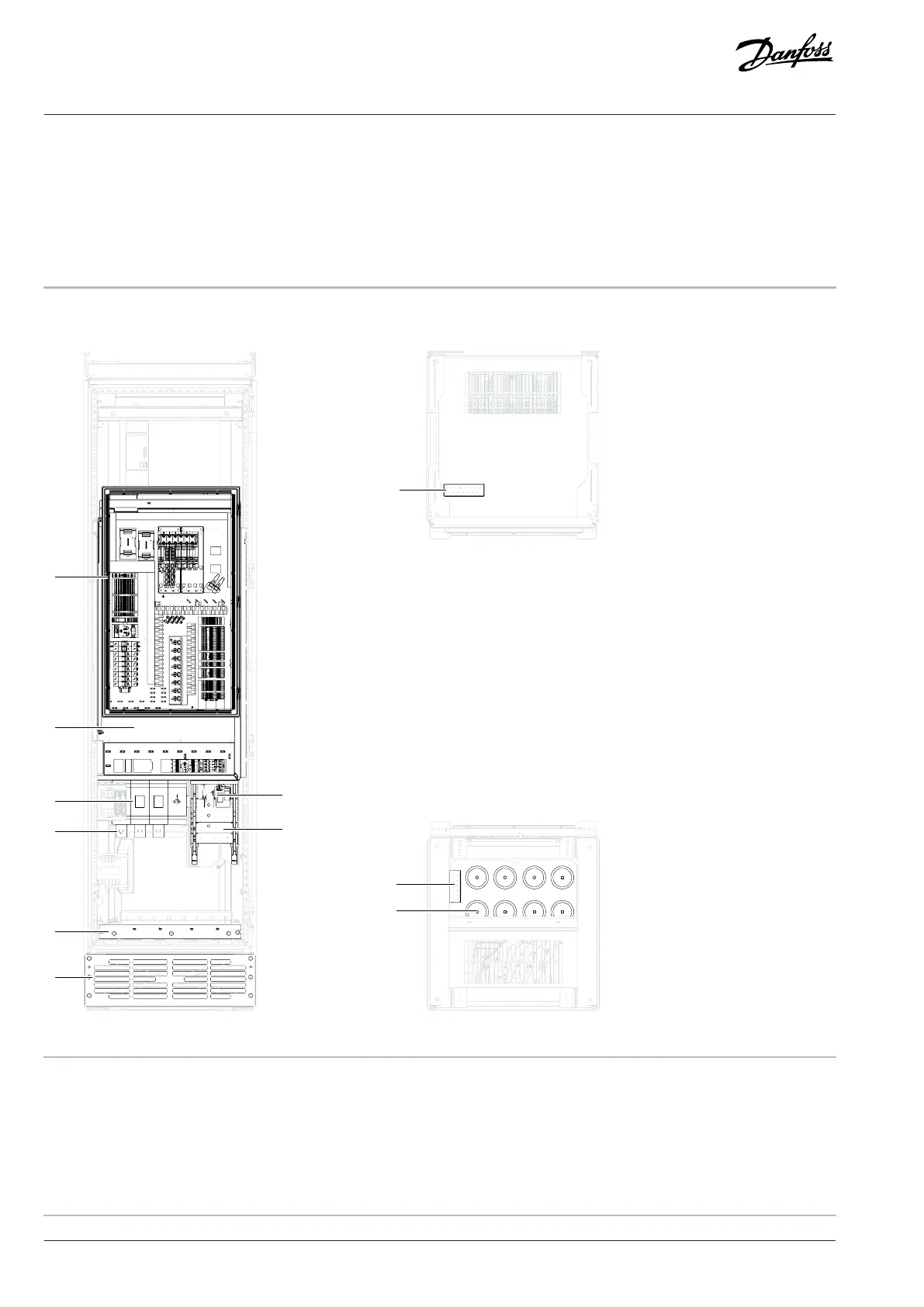
A View from the top
B View from the bottom
4.2.2 Interior View of the Cabinet, FE10
9
10
B
A
e30bl814.10
11
1
2
3
4
5
6
7
8
Figure 3: Interior View of FE10
1 Control compartment 2 Contactor (behind control compartment)
3 Main switch (optional) 4 Mains terminals
5 dU/dt Filter 6 Motor terminals
7 PE busbar 8 Inlet air grill
9 IP54 grommet for mains and motor cables (IEC) 10 Control cable grommet, bottom
18 | Danfoss Drives Oy © 2024.09 AJ389643274589en-000101 / 172F6409A
Design Guide | iC7-Automation Air-cooled Enclosed Drives Product Overview