Design Guide | iC7-Automation Air-cooled Enclosed Drives Control and Option Installation
Table 27: 24 V DC Voltage Output (continued)
Parameter Value
Short Circuit Current 250 mA
Electrical fast transient (EFT) 2 kV
7.7.8 Thermistor Input
The I/O and Relay Option contains 1 thermistor input. Thermistor input has basic isolation for system voltages ≤ 600 V and reinforced
isolation for system voltages ≤ 300 V (OVC III 3000 m). For system voltage of 600 V, supplementary insulation is necessary at the motor
end.
Table 28: Thermistor Input
Parameter Value
Electrical fast transient (EFT) 2 kV
Sensor R
trip
4.0 kΩ (PTC)
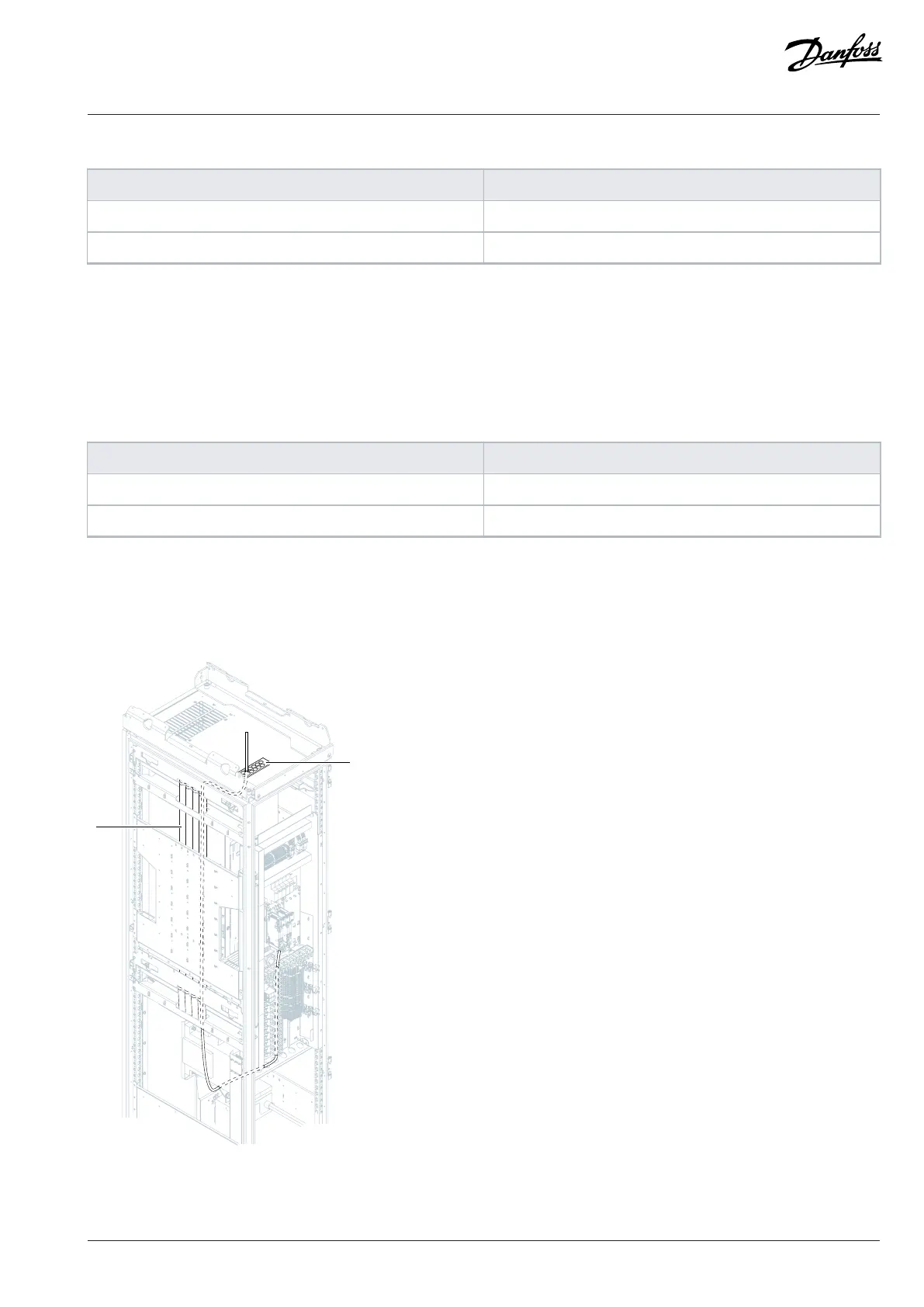
7.8 Control Cable Routing
Use the control cable grommets and tubes to route the control cables into the control compartment. There are control cable grommets
at the top and at the bottom of the cabinet.
Figure 40: Routing of Control Cables from the Top, FE9, FE10
Danfoss Drives Oy © 2024.09 AJ389643274589en-000101 / 172F6409A | 63