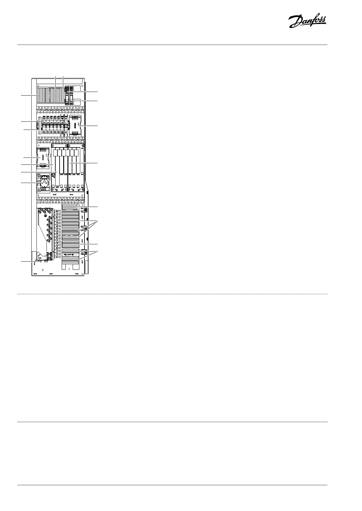
7.3 Control Compartment Internal Elements
1
9 10
11
12
3
4
14
15
16
17
2
5
13
7
8
e30bj689.11
6
4
Figure 32: Elements inside the Control Compartment, FE9
1 Mains contactor terminals (+GAC0) -XD0 2 Circuit breakers
3 Grounding terminals, -PE 4 24 V DC power supply (TB7, TB7.1)
5 Option Extender OC7F2 6 I/O and Relay Option OC7C1
7 230 V AC socket (CEE 7/3, +IGS0), or 115 V AC socket (US,
+IGS1), or 230 V AC socket (UK, +IGS2), -XD10
8 Ethernet ports for fieldbus X1 and X2
9 Auxiliary AC supply terminals (+IHAS), or auxiliary AC
voltage transformer terminals (+IHAT), -XD1
10 Cabinet heater terminals (+IBCH), -XD4
11 Auxiliary relay (+IBCH, +IAMH), -QAM 12 Auxiliary relay for door fan- QAB
13 Option slots 14 24 V DC terminals, -XD3
15 Spring-type terminals, -XD2.1, -XD2.2, -XD2.3 16 Door device terminals, -XDJ
17 Terminals for I/O and relay options
50 | Danfoss Drives Oy © 2024.09 AJ389643274589en-000101 / 172F6409A
Design Guide | iC7-Automation Air-cooled Enclosed Drives Control and Option Installation