Design Guide | iC7-Automation Air-cooled Enclosed Drives Control and Option Installation
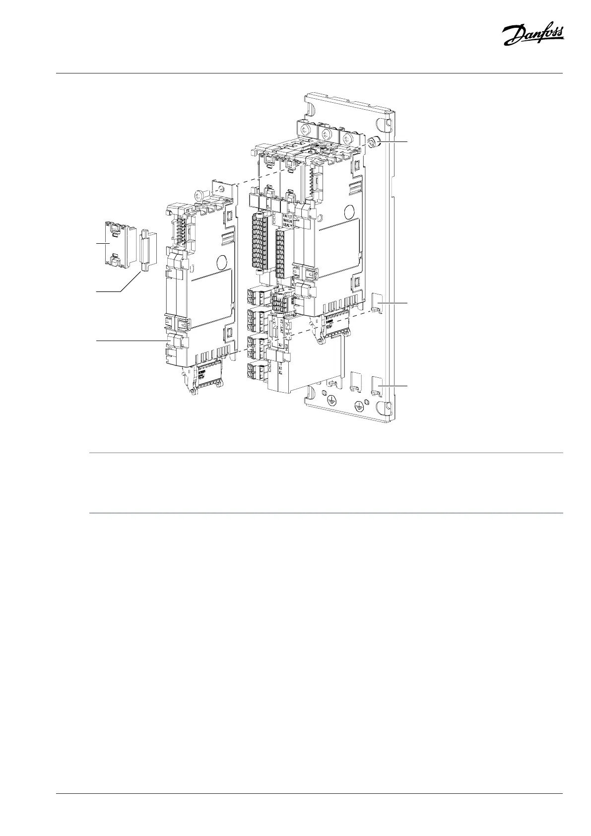
Figure 44: Installing a Board to the Modular Control Unit Mounting Plate
1 Option connector 2 Option terminal cover
3 Option board 4 Fixing point at the top
5 Fixing point at the middle 6 Fixing point at the bottom
3. Use the screw to attach the board to the fixing point at the top.
4. Attach an option connector to the newly installed board and the board next to it.
5. Attach option terminal covers to the empty terminals.
7.10 Installing the Control Cables
7.10.1 Requirements for the Control Cables
Requirements for the control cables:
l Wire size: 0.25–4 mm
2
(22–12 AWG)
l Wire size with end ferrule: 0.25–2.5 mm
2
(22–14 AWG)
l Wire stripping length: 10–12 mm (0.4–0.5 in)
Make sure that the control cables are long enough to prevent tight bends in the cables between the control compartment and the frame
of the drive. Use a flexible cable with fine-stranded wires meant for mobile installation.
7.10.2 Installing the Control Cables
1. Install the control cables into the option board or the terminal block.
Danfoss Drives Oy © 2024.09 AJ389643274589en-000101 / 172F6409A | 67