7 Control link status indicator 8 Ethernet speed indicator
9 Ethernet link activity indicator 10 Ethernet port (X7)
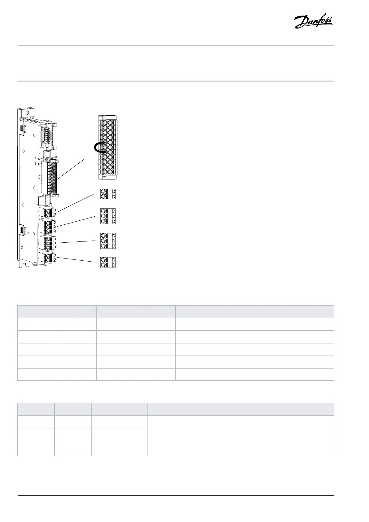
7.6 I/O and Relay Option Connections
11
13
15
17
19
21
23
31
33
35
37
12
14
16
18
20
22
24
32
34
36
38
X13
X51
X101
X102
X103
71
72
1
2
3
4
5
6
7
8
e30bh574.11
Figure 37: I/O and Relay Option Terminal Block and Terminal Numbering
Table 15: I/O and Relay Option Signals
Terminal Function Connector type
X13 I/O terminal 2 x 11 spring force connector 0.2–1.5mm
2
X51 Thermistor input 1 x 2 spring force connector 0.25–2.5mm
2
X101 Relay 1 1 x 3 spring force connector 0.25–2.5mm
2
X102 Relay 2 1 x 3 spring force connector 0.25–2.5mm
2
X103 Relay 3 1 x 2 spring force connector 0.25–2.5mm
2
Table 16: I/O Terminal Signals (X13)
Terminal Function Terminal block Description
11 +24 V
out
XD2.1:11
12 +24 V
out
XD2.1:12
Control voltage output.
24V DC (-15...+20%)
Maximum current 200mA
Short-circuit protected
56 | Danfoss Drives Oy © 2024.09 AJ389643274589en-000101 / 172F6409A
Design Guide | iC7-Automation Air-cooled Enclosed Drives Control and Option Installation