Design Guide | iC7-Automation Air-cooled Enclosed Drives Control and Option Installation
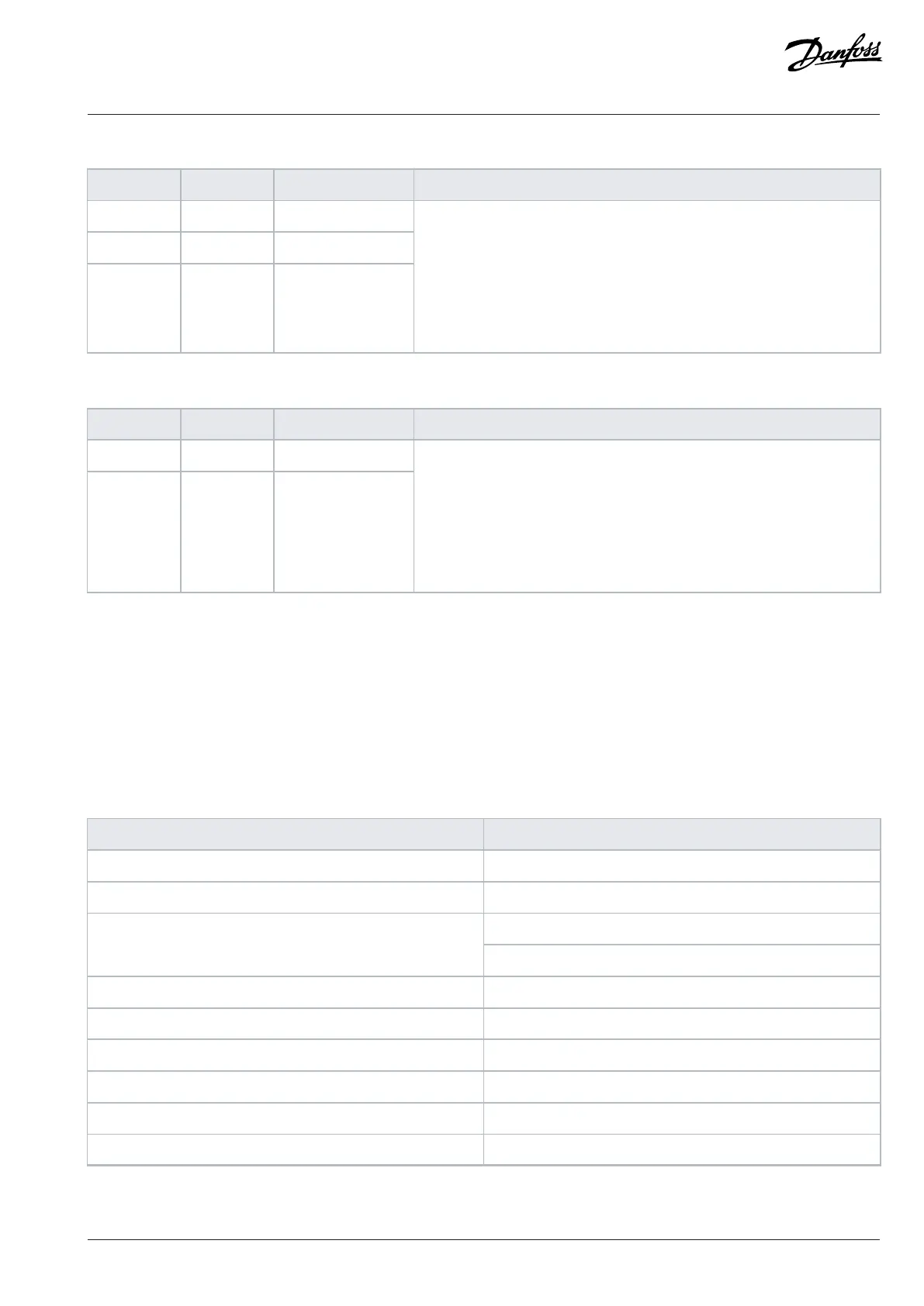
Table 19: Relay 2 Signals (X102)
Terminal Function Terminal block Description
4 COM XD2.1:4
5 NO XD2.1:5
6 NC XD2.1:6
Configurable relay output.
Switching capacity:
• 24V DC/8A
• 250V AC/8A
• 125V DC/0.4A
Minimum switching load: 5V/10mA
Table 20: Relay 3 Signals (X103)
Terminal Function Terminal block Description
7 COM XD2.1:7
8 NO XD2.1:8
Configurable relay output.
Switching capacity:
• 24V DC/8A
• 250V AC/8A
• 125V DC/0.4A
Minimum switching load: 5V/10mA
7.7 I/O and Relay Option Interface
7.7.1 Analog Inputs
The I/O and Relay Option has 2 analog inputs that can be configured with the software to voltage input or current input. The table shows
the specification for the analog inputs.
The analog inputs are protected in overvoltage conditions.
Table 21: Analog Input Types, Values, and Tolerances
Parameter Value
Measuring range: voltage mode -10...+10 V
Measuring range: current mode -20...+20 mA
Voltage mode ≈ 10 kΩInput impedance
Current mode ≈ 200 Ω
Accuracy 0.5% of full scale
Reaction time 0...90% step: < 1 ms
Number of inputs 2
Overvoltage limit +15/-15 V
Overcurrent limit +32/-32 mA
Electrical fast transient (EFT) 2 kV
Danfoss Drives Oy © 2024.09 AJ389643274589en-000101 / 172F6409A | 59