7 Auxiliary power cable 8 Control cable grommet
9 Mains cable 10 Grommets
11 Control board and option boards 12 Terminal blocks
13 Strain relief and 360° grounding 14 PE busbar
15 Motor cable 16 Brake cable
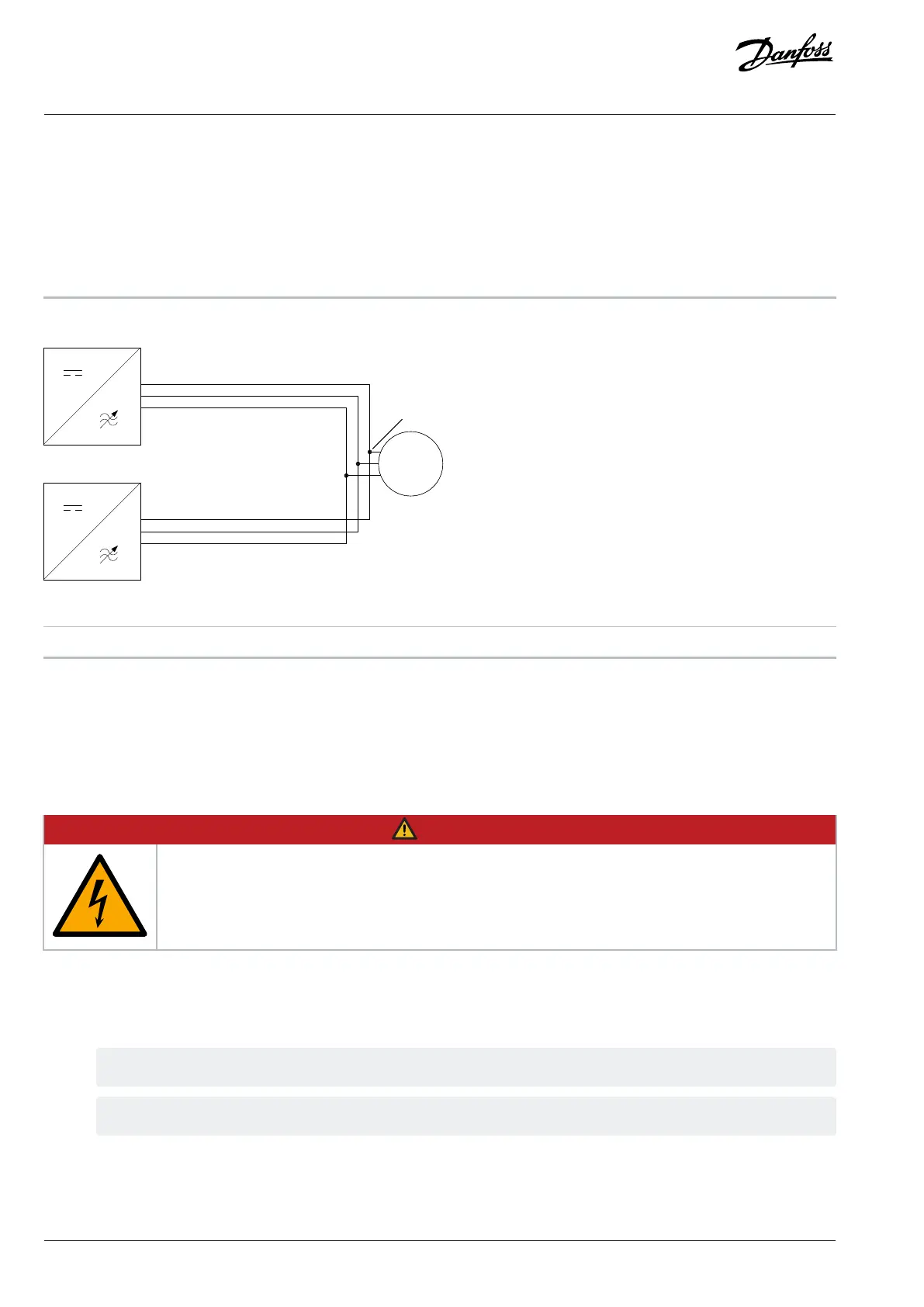
Figure 24: Recommended Installation
1 Inverter module 2 Common coupling point at the motor terminals
If the drives are connected in parallel without output filters or only with a common-mode filter, the recommended common coupling
point of motor cables is at the motor terminals.
6.6 Installing Power Cables
6.6.1 Installing the Power Cables through the Bottom
DANGER
ELECTRIC SHOCK
There are live components behind the touch protections. Lack of touch protections can cause death or serious
injury.
l After power cabling, reinstall all touch protections at their original places.
1. Lift the service table all the way up until it is locked.
2. Strip the mains and motor cables.
3. In an IP54 installation, make openings for the cables in the grommets on the bottom of the cabinet.
This instruction applies for IEC installations.
The grommets must be suited to the output diameter of the cable. The cable diameter is 25–65 mm (1–2.6 in).
4. Lead the power cables through the grommet holders.
5. Peel the cable shield and attach the end to the PE busbar.
6. Use cable clamps to fix the cables.
42 | Danfoss Drives Oy © 2024.09 AJ389643274589en-000101 / 172F6409A
Design Guide | iC7-Automation Air-cooled Enclosed Drives Electrical Installation