Design Guide | iC7-Automation Air-cooled Enclosed Drives Specifications
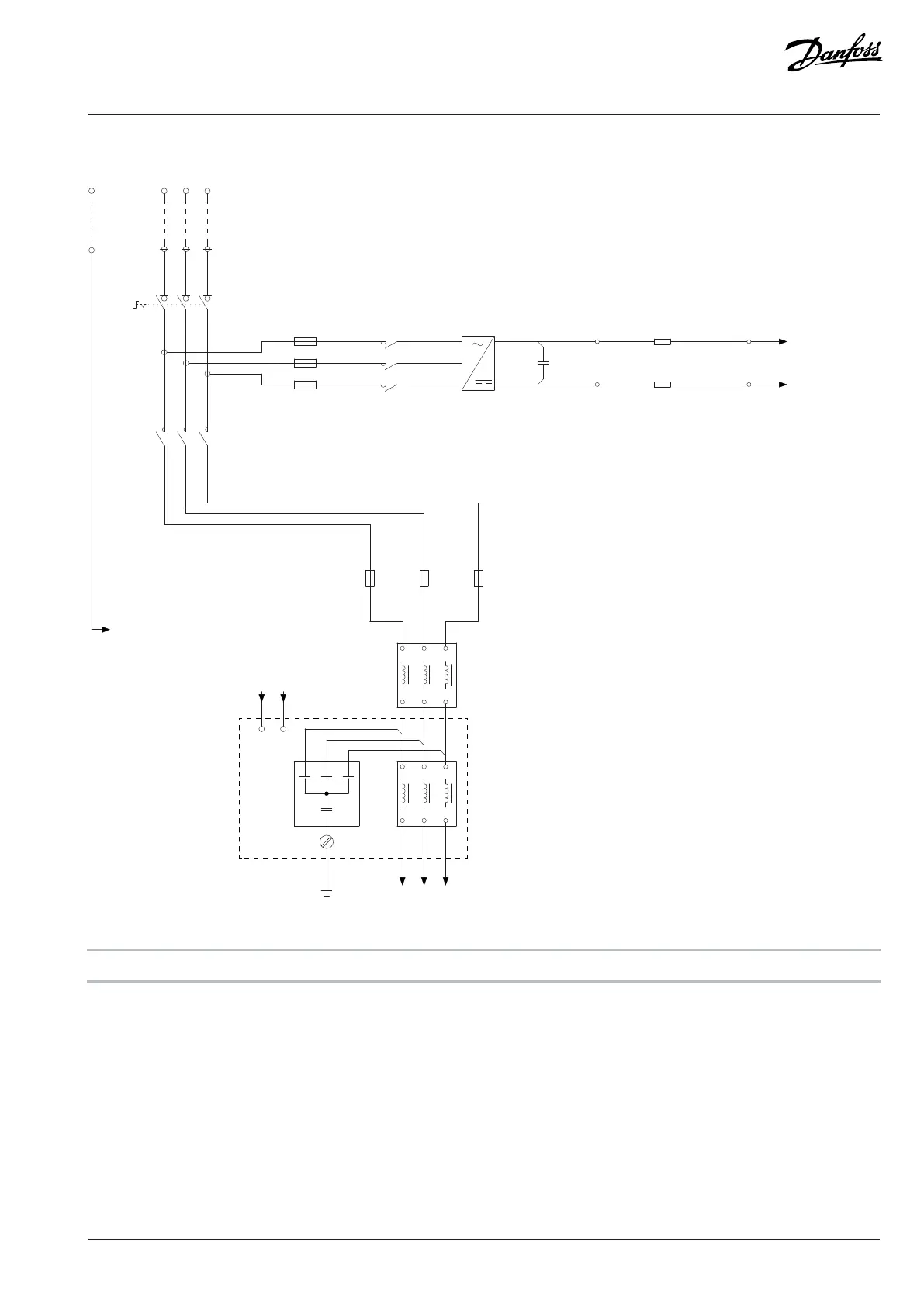
9.3.2 Wiring Diagram, AE10+IE10, 385–590 A
L1 L2 L3
L1' L2' L3'
-RF4.1
-X121:+
FAN DC+
-
FAN DC-
PE
L1 L2 L3
-RF4.1
L1 L2 L3
L1' L2' L3'
-PE
1
2
3
4
5
1 3 5
6
2 4 6
-QA3
-QB0
1
2
-FC1.2
1
2
-FC1.1
1
2
-FC1.3
PE
L1 L2 L3
1
3
5
-QB6
32A
1
-QA6
3
5
L1
L2
L3
-TB6
1600V
80A
3
-CA6
300nF
-RA6.2
5.5Ω
-RA6.1
5.5Ω
2+
-XD6
4-
-XD6
3-
-XD6
1+
-XD6
DC+
DC-
FAN1+
FAN1-
1L2
1L1
1L3
PE
2 2 +
-
4
6
4
6
A
B
e30bj485.11
Figure 71: Wiring Diagram, AE10+IE10, 385–590 A
A L Filter B LC Filter
Danfoss Drives Oy © 2024.09 AJ389643274589en-000101 / 172F6409A | 97