Design Guide | iC7-Automation Air-cooled Enclosed Drives Electrical Installation
A B
1
5
2
3
4
1
5
6
7
2
3
4
e30bl785.10
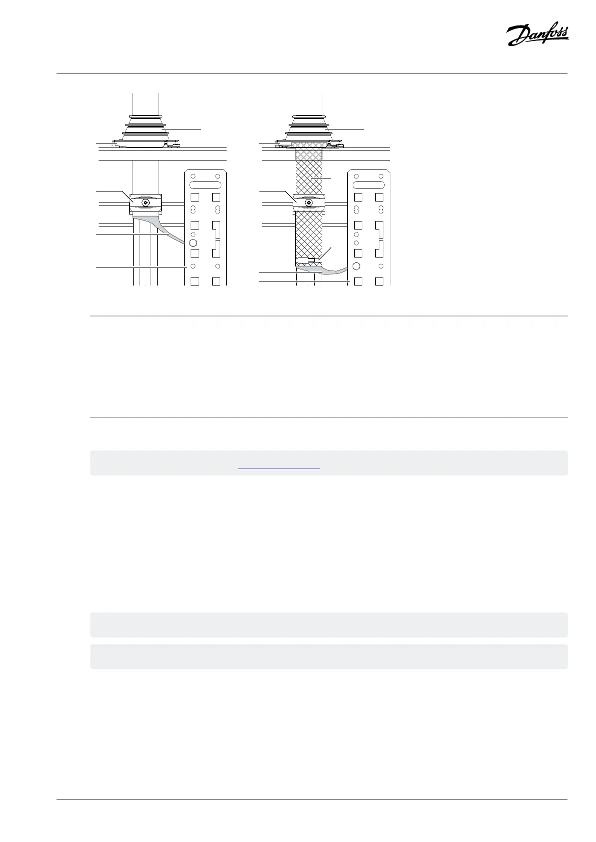
Figure 27: Cabling Methods (IEC)
1 Grommet holder 2 Cable clamp
3 Cable shield 4 PE busbar
5 Grommet 6 Knitted metal mesh tube
7 Cable tie A IP54
B EMC 360° (IP54 and knitted metal mesh tube)
7. Connect the mains cables to the terminals L1, L2, and L3, and the motor cables to the terminals U, V, and W.
See the correct tightening torques in 9.1 Tightening Torques.
8. Connect the grounding conductors to the PE busbar.
6.7 Installing the Brake Cables, FE9, FE10
1. Strip the brake cables.
2. To make a 360° connection, expose the shield of the cables.
3. Peel the cable shield and attach the end to the PE busbar.
4. Use cable clamps to fix the cables.
5. Find the brake terminals in the system module inside the cabinet. Connect the brake cables to the brake terminals.
Use M10 bolts.
Use the tightening torque 19 Nm (168 in-lb).
Danfoss Drives Oy © 2024.09 AJ389643274589en-000101 / 172F6409A | 45