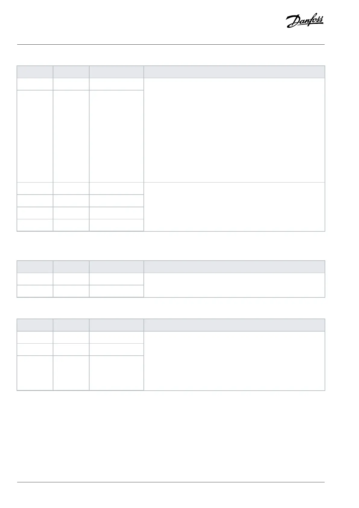
Table 16: I/O Terminal Signals (X13) (continued)
Terminal Function Terminal block Description
33 AI 1 XD2.1:33
34 AI 2 XD2.1:34
Configurable analog input.
Voltage mode:
• 0 ± 10V
• single-ended
• R
i
~ 10kΩ
• accuracy ± 0.5% of full scale
Current mode:
• 0 ± 20mA
• differential
• R
i
~ 200Ω
• accuracy ± 0.5% of full scale
35 GND XD2.1:35
36 GND XD2.1:36
37 GND XD2.1:37
38 GND XD2.1:38
I/O ground.
Ground for digital outputs, +10V Ref, +24V
out
, analog inputs, and analog
outputs.
1) Digital outputs are not recommended for main circuit breaker control, use relay outputs instead.
Table 17: Thermistor Input Signals (X51)
Terminal Function Terminal block Description
71 TI+ XD2.1:71
72 TI- XD2.1:72
Thermistor input, galvanically isolated. R
trip
= 4kΩ
Table 18: Relay 1 Signals (X101)
Terminal Function Terminal block Description
1 COM XD2.1:1
2 NO XD2.1:2
3 NC XD2.1:3
Configurable relay output.
Switching capacity:
• 24V DC/8A
• 250V AC/8A
• 125V DC/0.4A
Minimum switching load: 5V/10mA
58 | Danfoss Drives Oy © 2024.09 AJ389643274589en-000101 / 172F6409A
Design Guide | iC7-Automation Air-cooled Enclosed Drives Control and Option Installation