Design Guide | iC7-Automation Air-cooled Enclosed Drives Control and Option Installation
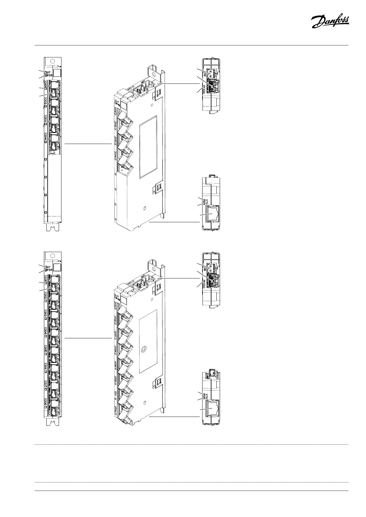
Figure 35: Terminal and Indicator Light Locations on the 4-port Star Coupler Board
Figure 36: Terminal and Indicator Light Locations on the 8-port Star Coupler Board
1 Board configuration status indicator 2 +24 V power status indicator
3 Power unit connection status indicators 4 Fiber connection to the power unit (X301–X316)
5 +24 V power supply (X65) 6 Fiber connection to the control board (X90)
Danfoss Drives Oy © 2024.09 AJ389643274589en-000101 / 172F6409A | 55