Design Guide | iC7-Automation Air-cooled Enclosed Drives Control and Option Installation
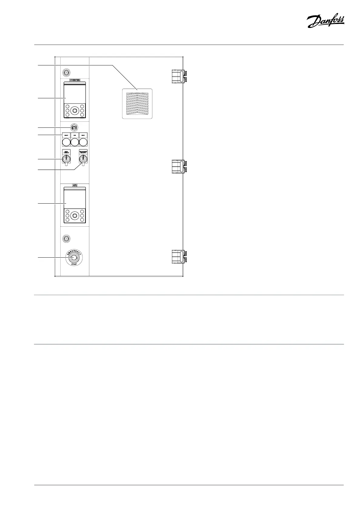
Figure 31: Control Compartment Door Elements, AE10/11, IE10/11
1 Filter cover and optional IP54 filter (+IP54) 2 Control panel (for the inverter module), -PGA
3 Ethernet port (for the inverter module), RJ45 4 Run, ready, and fault lights (+IICD), -PF3, -PF4, -PF5
5 Mains 0–enable switch, -SF11 6 Pre-charging MAN–AUTO switch, -SF12
7 Control panel (for the AFE module), -PGA2 8 Emergency stop button (+ILSS), -SFG
Danfoss Drives Oy © 2024.09 AJ389643274589en-000101 / 172F6409A | 49