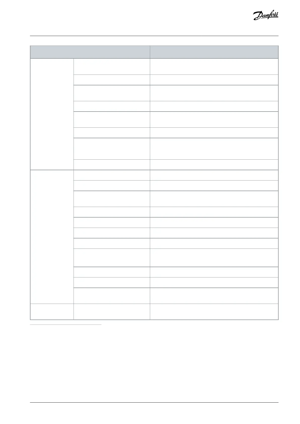
Technical item or function
0(4)…20 mA, R
i
= 250 W differential; Resolution 0.1%, accuracy
±1%
Positive or negative logic; 18…30 V DC
+24 V, ±15%, max volt. ripple < 100 m Vrms; maximum 250 mA
Dimensioning: Maximum 1000 mA/control box
+10 V, ±3%, maximum load 10 mA
0(4)…20 mA; RL maximum 500 W; Resolution 10 bit; Accuracy
±2%
Open collector output, 50 mA/48 V
2 programmable change-over relay outputs Switching capacity:
24 VDC/8 A, 250 VAC/8 A, 125 VDC/0.4 A Min. switching load: 5
V/10 mA
Galvanically isolated, Rtrip = 4.7 kΩ
NX_5: 911 V DC; NX_6: 1200 V DC
NX_5: 333 V DC; NX_6: 460 V DC
If there is a ground fault in motor or motor cable, only the AC
drive is protected
Trips if any of the input phases is missing
Trips if any of the output phases is missing
Unit overtemperature protection
Motor overload protection
Yes
(2)
Motor overload protection provided at 110% of full load current
Motor underload protection
Short-circuit protection of +24 V and
+10 V reference voltages
Drive enclosure ma-
terials
Dark grey = NCS 7010-R90B (Pantone 7546C)
1
The rated currents in given ambient temperatures are achieved only when the switching frequency is equal to or less than the factory default.
Thermal management can reduce the switching frequency.
2
System software version NXP00002V186 (or newer) must be used for the motor thermal memory and memory retention functionality to conform
to UL 508C requirements. If an older system software version is used, motor overtemperature protection is required at installation to comply with UL
requirements.
AQ351737303996en-000201 / DPD00888 | 149Danfoss A/S © 2023.09
Specifications
VACON® NXP IP00 Drive Modules
Operating Guide

 Loading...


