165
Torque Settings
Screws securing certain components in the system require being tightened to specific torque values.
Table 29 shows the chassis’ torque settings.
Table 29. Torque Settings
Component Torque Component Torque
Processor Heat sink 0.67 N-m (6 in-lb)
Peripheral board
0.90 N-m (8 in-lb)
Main board
0.67 N-m (6 in-lb)
SCSI Back plane Board
0.67 N-m (6 in-lb)
Processor Power Pod
0.67 N-m (6 in-lb)
Peripheral board
0.67 N-m (6 in-lb)
PCI Riser Board
0.67 N-m (6 in-lb)
Processor Air Duct
0.67 N-m (6 in-lb)
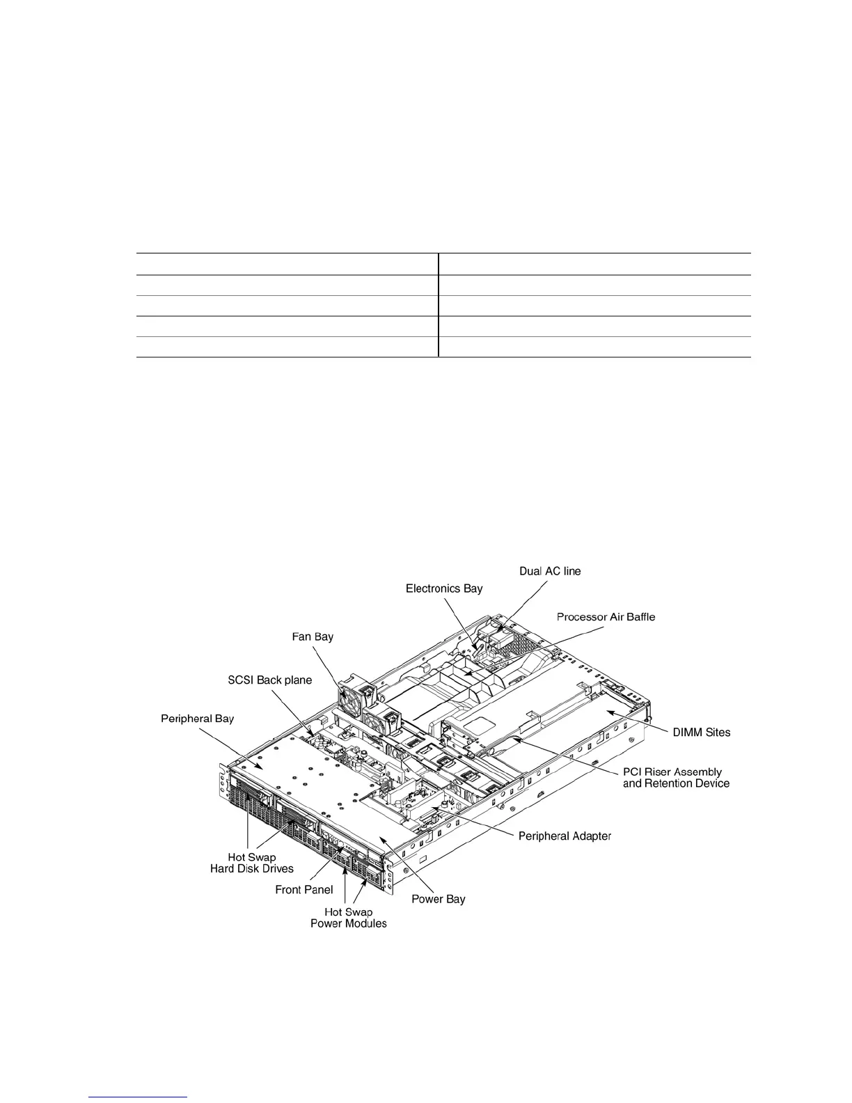
Identifying Chassis Modules
Figure 51 shows the chassis with the top cover removed. Several component areas can be
identified, including the processor air duct, memory area (eight DIMM sites, obscured), the PCI
riser assembly, the electronics bay (E-Bay), and the peripheral bay. In addition, the chassis
supports three hot-swap power supplies, six fans, three PCI cards, one ATA DVD / CD-ROM
drive, and two SCSI (SCA-2) hard drives.
Figure 51. Locating System Modules