42
Processor Sockets
Each Intel Itanium 2 processor plugs into a 700-pin Zero Insertion Force (ZIF) socket. Each
processor is powered by a 12-V power pod located adjacent to the processor on the main board.
Attached to the top of each processor is a heat sink that dissipates thermal energy.
Memory Subsystem
The basic architecture of the memory subsystem is as follows:
• The DIMMs reside on the main board, between the PCI riser assembly and the chassis.
• Four Rambus channels run from the Scalable Node Controller (SNC) to each of the four
Memory Repeater Hubs (MRH-D).
• There is one MRH-D device per Rambus channel.
• Each MRH-D supports two DDR branch channels.
• Each DDR branch channel supports two 184-pin DDR DIMMs.
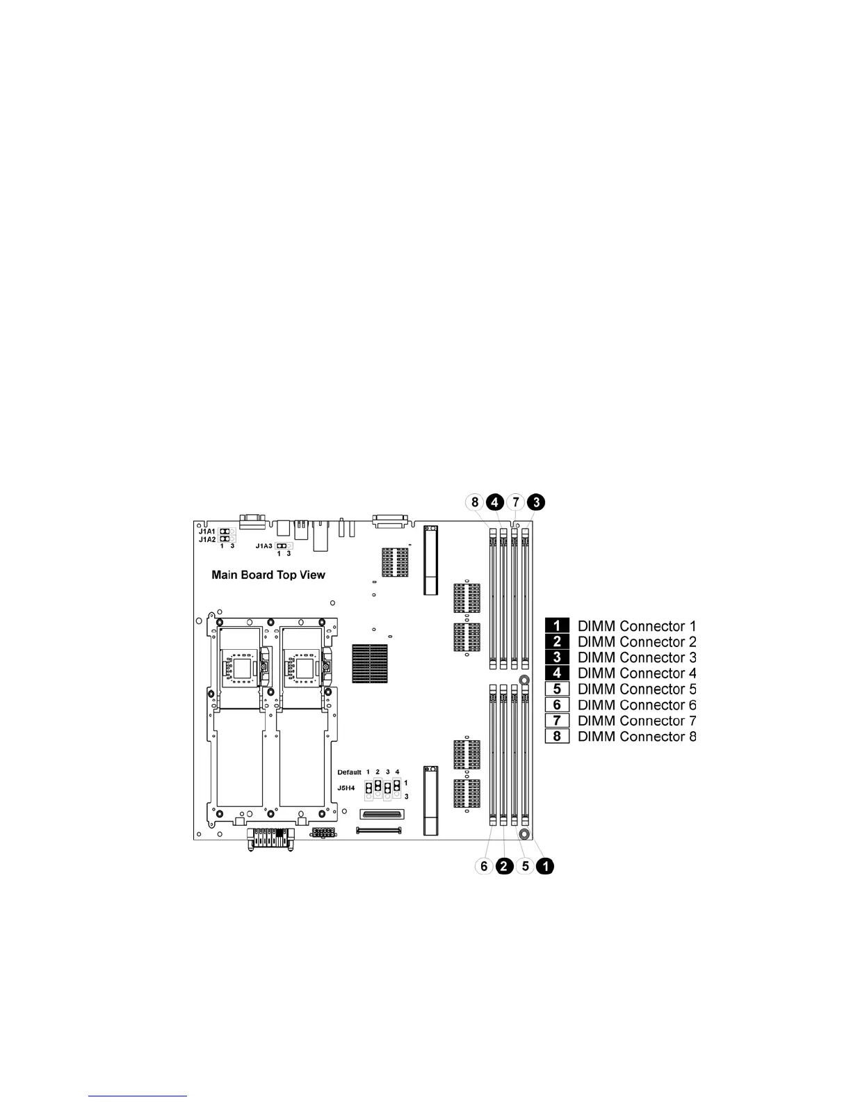
• The server system includes eight DIMM connectors in two rows.
• Each row of DIMM sockets supports four DDR DIMMs, one channel of each MRH-D, which
collectively make up a cache line.
The DIMM socket locations are shown in Figure 17.
Figure 17. Location of Memory DIMMS