32
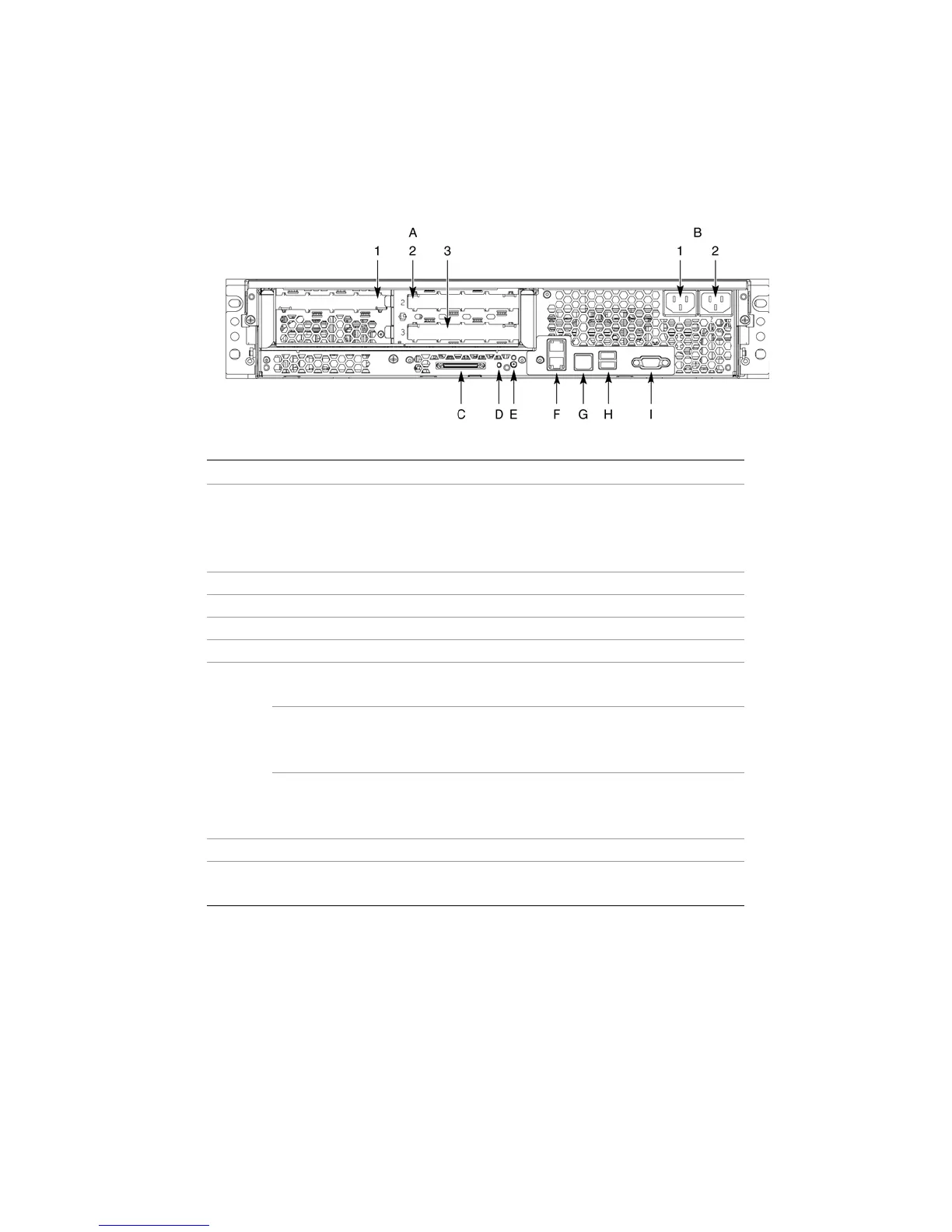
Chassis Rear
Figure 10 shows the rear of the system.
Callout Description
PCI Slots
Slot 1 100-MHz, 64-bit PCI-X slot, full length
Slot 2 100-MHz, 64-bit PCI-X slot, full length
A
Slot 3 133-MHz, 64-bit PCI-X slot, full length
B AC input power connectors (two)
C External SCSI connector
1
D System ID switch
E System ID LED (blue)
Two LAN ports, RJ45 connector (LAN1 on bottom, LAN2 on top)
LAN port LEDs:
Status LED (Green) On – Ethernet link is detected
Off – no Ethernet connection
Blinking – Ethernet link is active
F
Speed LED
(Green/Amber)
Off – 10 Mbps
Green On – 100 Mbps
Amber On – 1000 Mbps
G Serial port
2
, RJ45 connector
H Two USB 1.1 ports, 4-pin connectors (USB0 on bottom, USB1 on top)
I Video port, standard VGA compatible, 15-pin connector
Notes:
1. External SCSI bus supports both LVDS and SE signals via the external SCSI connector.
2. EMP access is provided via shared serial port.
Figure 10. Chassis Rear Features