36
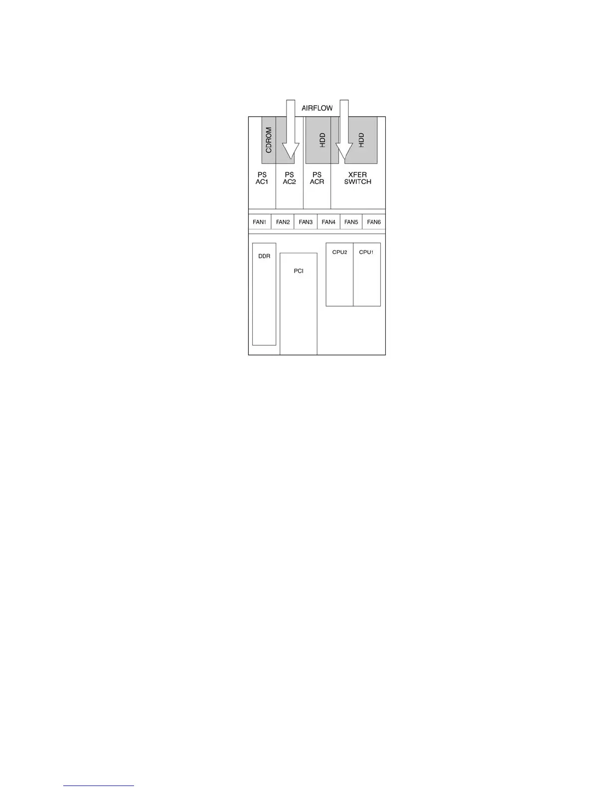
Figure 14 shows the cooling subsystem layout with the airflow direction indicated.
Figure 14. Cooling Subsystem Layout
The server system supports only a fully populated system fan configuration. However, the system
will continue to meet thermal specifications with either a system fan or a power supply failure. The
power supply redundancy feature applies to systems with three power modules installed.
If a fan fails, system cooling is maintained and the system continues to operate while the failed fan
is being hot-swapped. All system fans have tachometer output, internal speed control, and external
Pulse Width Modulation (PWM) speed control.
A failure is detected when the RPM of a fan falls below a predetermined minimum threshold
(Approx. 5000 RPM). If a system fan falls below this threshold, all fans will be boosted to operate
at a higher speed (Approx. 8500 RPM)
The fans will also be boosted to the higher speed if a power supply fails for any reason (including
loss of AC power). The fans will not be boosted if the Redundant (ACR) power supply fails. If the
redundant power supply fails, the system fans will not be affected.
When boosted, all fans remain at high speed until the failed fan or power supply is replaced. When
a fan replacement is detected by a change in state of the fan presence signal. After a failed fan is
replaced, the fans return to the lower speed and fan failure monitoring at the lower speed levels is
reactivated.
When a power supply fails and is replaced, the replacement is detected by server management.