184
4. Connect one side of the Y-cable to the power pod and verify that the Y-cable connects to all
installed power pods.
5. Install the thermal blank (in a single processor configuration only).
6. Reinstall the processor air duct and secure it by tightening the four captive screws.
7. Follow the instructions under Installing the Top Cover.
Adding or Replacing Memory DIMMs
NOTE
The BIOS automatically detects, sizes, and initializes the memory array, depending
on the type, size, and speed of the installed DIMMs. The BIOS reports memory size
and allocation to the system through configuration registers. The system does not
support mixed-sized DIMMs or DIMMs from different vendors within the same row.
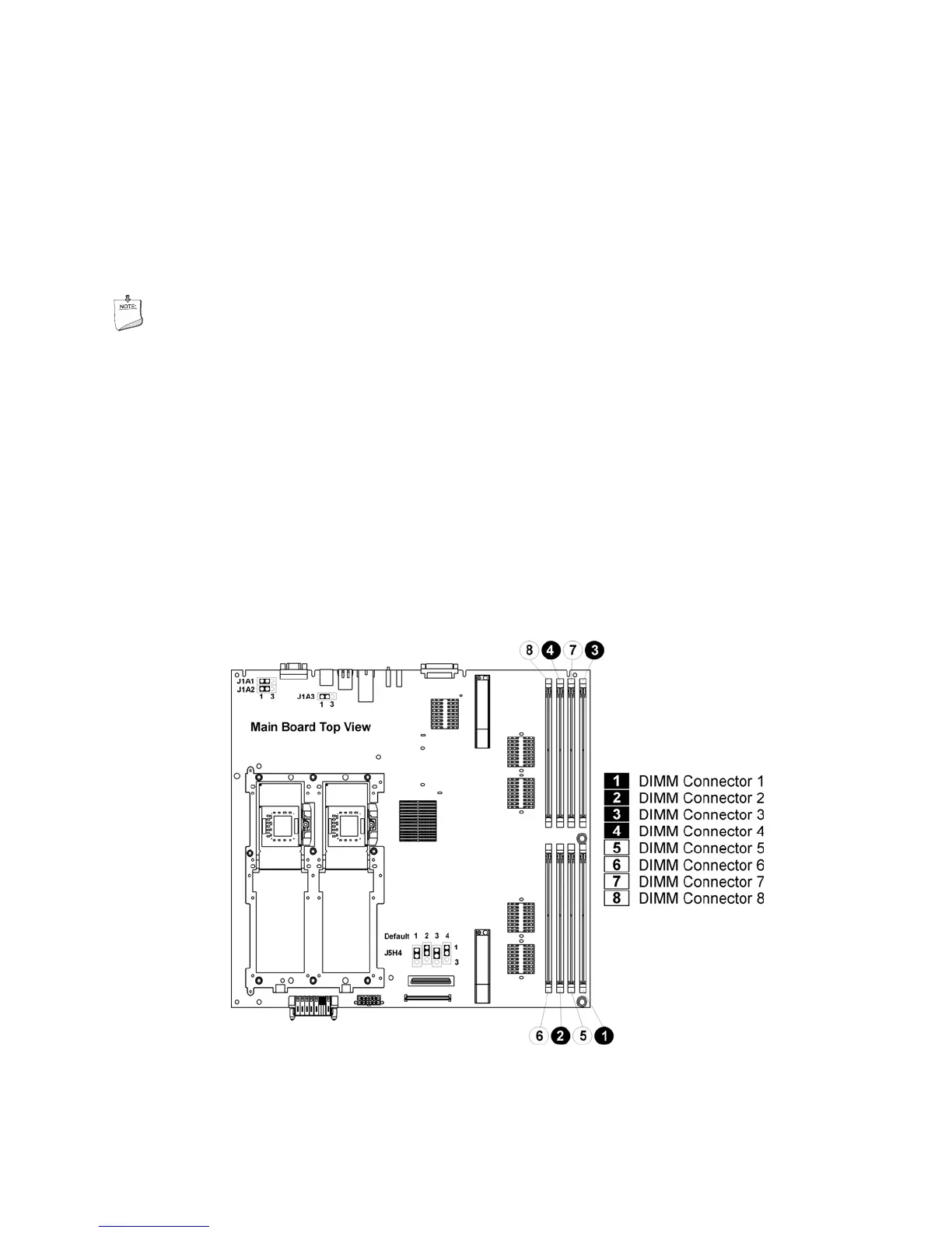
Figure 64 shows the locations of the DIMMs on the main board. Row 1 consists of DIMM sockets
1 – 4; row 2 consists of DIMM sockets 5 – 8. When replacing DIMMs, the following rules must be
followed:
• DIMMs must be populated in groups of four, referred to as a row.
• Within a single row, all DIMMs must be identical. (Identical DIMM size and identical number
of devices on the DIMM).
• Each of the two possible DIMM rows can be populated with different technologies.
• For best performance, the amount of memory on each MRH-D DDR branch channel should be
the same to enable the benefits of memory interleaving.
Figure 64. Location of Memory DIMMS