FrameMaker Ver5.5E(PC) Di152/Di183 MECHANICAL/ELECTRICAL
01.09.05
M-19
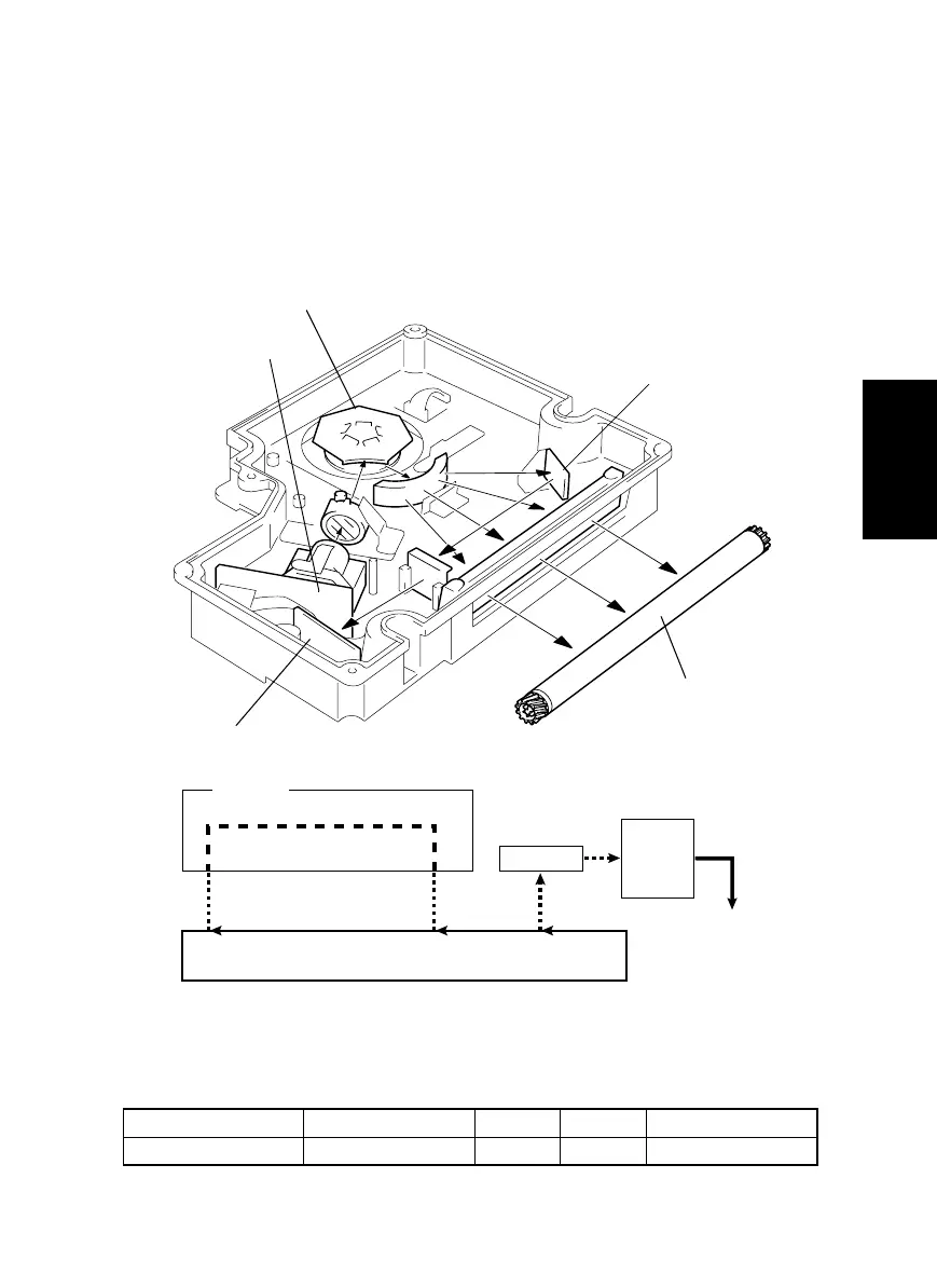
11-1. Laser Exposure Process
1. The Start key is pressed.
2. The laser diode is forced to turn ON and the laser intensity is automatically adjusted.
3. The SOS Sensor Board is illuminated by the laser beam, which generates an SOS sig-
nal.
4. The SOS signal determines the laser emission timing for each main scanning line.
5. The surface of the PC Drum is illuminated by the laser beam corresponding to the
image data, which forms an electrostatic latent image.
Elevtrical Component Control Signal ON OFF Wiring Diagram
M2 PWB-A PJ13A-3 L H 8-D
4021M016AA
PC Drum
SOS Mirror
SOS Board
LD Board PWB-B
Polygon Motor M2
PC Drum
SOS
Sensor
SOS Signal
SOS Mirror
DCBA
A to B: LD activation
B to C: LD OFF
C to D: Laser beam exposure area according to the image data
1171M038AA