FrameMaker Ver.5.5E(PC) DIS/REASSEMBLY, ADJUSTMENT FOR Di152/Di183
01.09.03
D-10
Job Tray (JS-202): Option
Shifting Unit (OT-103): Option
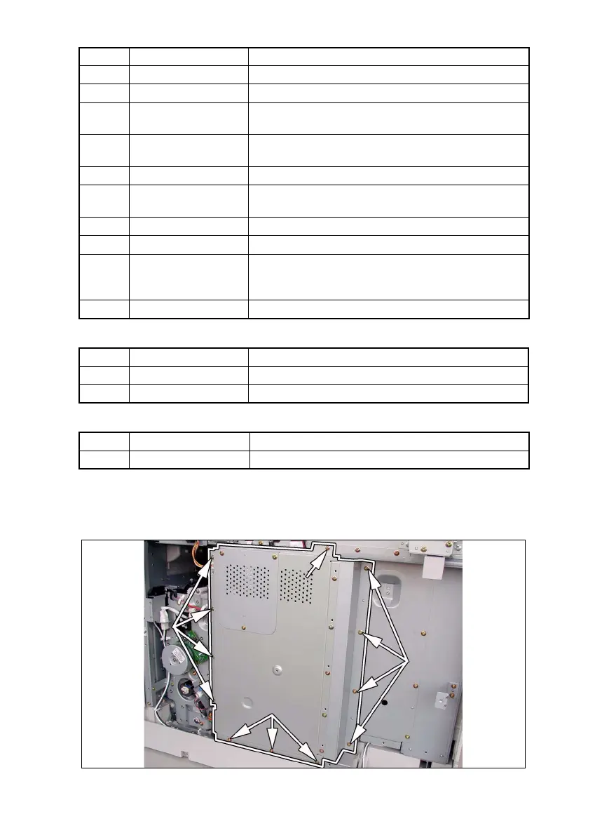
(1) Removal of the Master Board
1. Remove the Rear Cover.
2. Remove 12 screws and the PWB Cover Assy.
Symbol Part Name Removal Procedure
PWB-A Master Board ☞ D-10
PWB-C Control Board ☞ D-11
PWB-I
Paper Size Detecting
Board
Remove the Rear Cover.
→ Remove the PWB Assy. →
Remove two screws and the PWB-I Assy.
→ PWB-I
PWB-J CCD Board
☞ D-23
✽ Remove the CCD Unit as a unit.
PWB-R1 Fusing Board Remove the Fusing Unit.
→ PWB-R1
PWB-R2
Pre-Image Transfer
Board
Open the Right Door.
→ PWB-R2
PU1 DC Power Supply ☞ D-13
PU2 Inverter Board ☞ D-23
PU3 Control Panel
Remove two control panel mounting screws.
→
Remove two ground wire mounting screws.
→ Remove
one flat cable and unplug one connector. → PU3
HV1 High Voltage Unit ☞ D-11
Symbol Part Name Removal Procedure
PWB-A Main Board ☞ D-46
PWB-B Paper Detecting Board ☞ D-48
Symbol Part Name Removal Procedure
PWB-A Main Board ☞ D-49