FrameMaker Ver5.5E(PC) Di152/Di183 MECHANICAL/ELECTRICAL
01.09.05
M-47
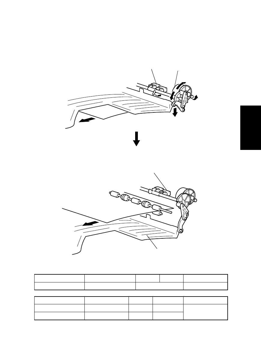
20-1. Tray Selecting Mechanism
• Paper is fed into either the Exit Tray of the machine or the Job Tray. Either is selected
according to the application mode (fax, copier, or printer).
• The specific tray in which paper is fed is selected by a motor and a sensor.
Elevtrical Component Control Signal ON OFF Wiring Diagram
M1 PWB-A PJ2A-1 to 4 Pulse output 16-A
Elevtrical Component Control Signal Activated Deactivated Wiring Diagram
PC32 PWB-A PJ4A-3 L H
16-B
PC33 PWB-A PJ4A-6 L H
<When feeding paper into the Exit Tray: Copier>
<When feeding paper into the Job Tray: fax/printer>
4021M047AB
4021M046AB
Upper Home Sensor PC32: Activated
Bin Switching Motor M1
Paper
Lower Home Sensor PC33: Activated
Job Tray
Paper
(M1: Backward Rotation)