CHAPTER 2
Eddy Current Brake
Above Ground Model 200iX/250iX Motorcycle Dynamometer Installation Guide
2-20
3 Keeping the panels parallel, slide the eddy current brake towards the dyno. Slide
the driveline over the key on the dyno shaft. You will need to support the driveline
as you slide it onto the dyno shaft.
4 Continue sliding the eddy current brake towards the dyno until the covers on the
brake and dyno are flush.
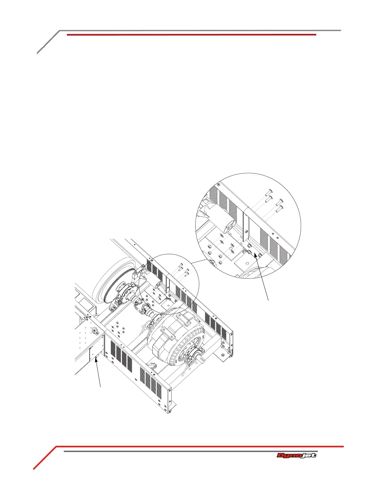
5 Secure the connector plate to the dyno frame using the four bolts, washers, and
nuts removed earlier. There is a connector plate on either side of the brake. Refer
to Figure 2-15.
Note: Do not tighten the bolts.
6 Verify the covers on the brake and the dyno line up. These covers must be flush
and parallel. If these covers are not flush, place shims between the floor and the
eddy current brake or the dyno until they are flush.
7 Once aligned, tighten all connector plate bolts and nuts.
Figure 2-15: Secure the Connector Plates
three bolts not visible
from this view
connector plate