4 PKE-SWD-32, interface for motor-starter combination with PKE PKE12/32
4.9 Programming
SmartWire-DT module IP20 01/20 MN05006001Z-EN www.eaton.com 111
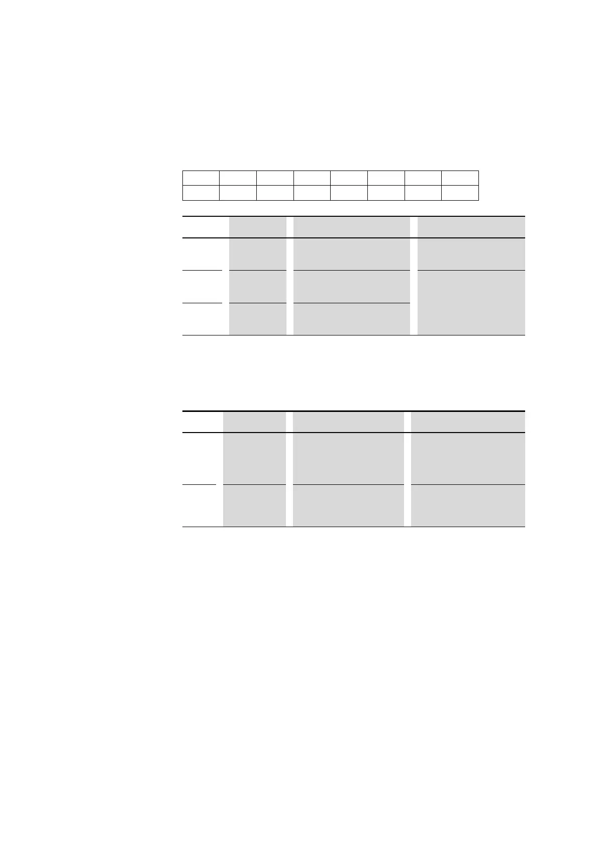
4.9.1.2 Outputs
Byte 0:
Contactor activation, ZMR, ZMR operating mode
4.9.1.3 Diagnostics
During diagnostics (input byte 0, bit 4 is set) the module signals the following
causes of faults via three device-specific fieldbus diagnostics states:
4.9.1.4 Set value I
r
The overload release value set on the PKE basic device is indicated via bit
field I
r
(input byte 1, bit 0, ..., 3). The value of this bit field indicates the set
absolute current value of the overload release that varies according to the
PKE trip block selected. Bit field I
r
has the following meaning for the different
PKE trip blocks:
76543210
––––ZMR H/AZMR–Q0
Data bit
Designation Description Notes
0 Q0 Contactor actuation
0: Contactor OFF
1: Contactor ON
–
2
ZMR Activation of ZMR function
0: Deactivation of ZMR function
1: Activation of ZMR function
→ Section 4.9.2, "Overload relay
function (ZMR)", page 115
3
ZMR H/A Operating mode ZMR-Function
0: Manual function
1: Automatic function
Value Description Remedy Notes
0x03 No communication
between PKE-
SWD-32 and PKE
trip block
• Check whether the PKE trip block
used is of part no. PKE-XTUA-….
• Check the terminals of the PKE32-
COM and connect the PKE32-
COM if necessary.
During this state, the module can be
still used for activating the connected
contactor. In case of overload, the
main current paths are disconnected
by the PKE.
0x15
No unambiguous
position of the 1-0-
A switch for more
than 4 seconds
• Move the 1-0-A switch to one of
the three defined positions.
In this state the connected contactor
is switched off. With bit field A1, A2
the value 0x00 is reported.

 Loading...


