7.7 Terminal assignment of the CAN bus terminals
For further details about the setting of the CAN bus address see chapter Setting the CAN bus address.
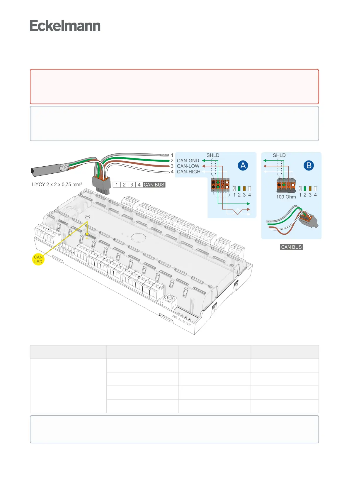
Controller type Terminal No. CAN bus Wire colour
All controllers 1 Shield (SHLD) Shield
2 CAN-GND green
3 CAN-LOW brown
4 CAN-HIGH white
Warning about dangerous electrical voltage!
If mains voltage is connected to the CAN bus terminals, this will result in the destruction of all
components connected to the CAN bus!
All supply lines from and to the case controller, particularly those of the CAN bus, must be shielded
(cable type: LiYCY)! As a general rule, care should be taken to ensure that signal cables and cables
carrying mains voltage are routed in separate cable channels.
The orange CAN bus LED always flashes when data are being exchanged via the CAN bus with the
system centre / store computer; see chapter Status LEDs for details.