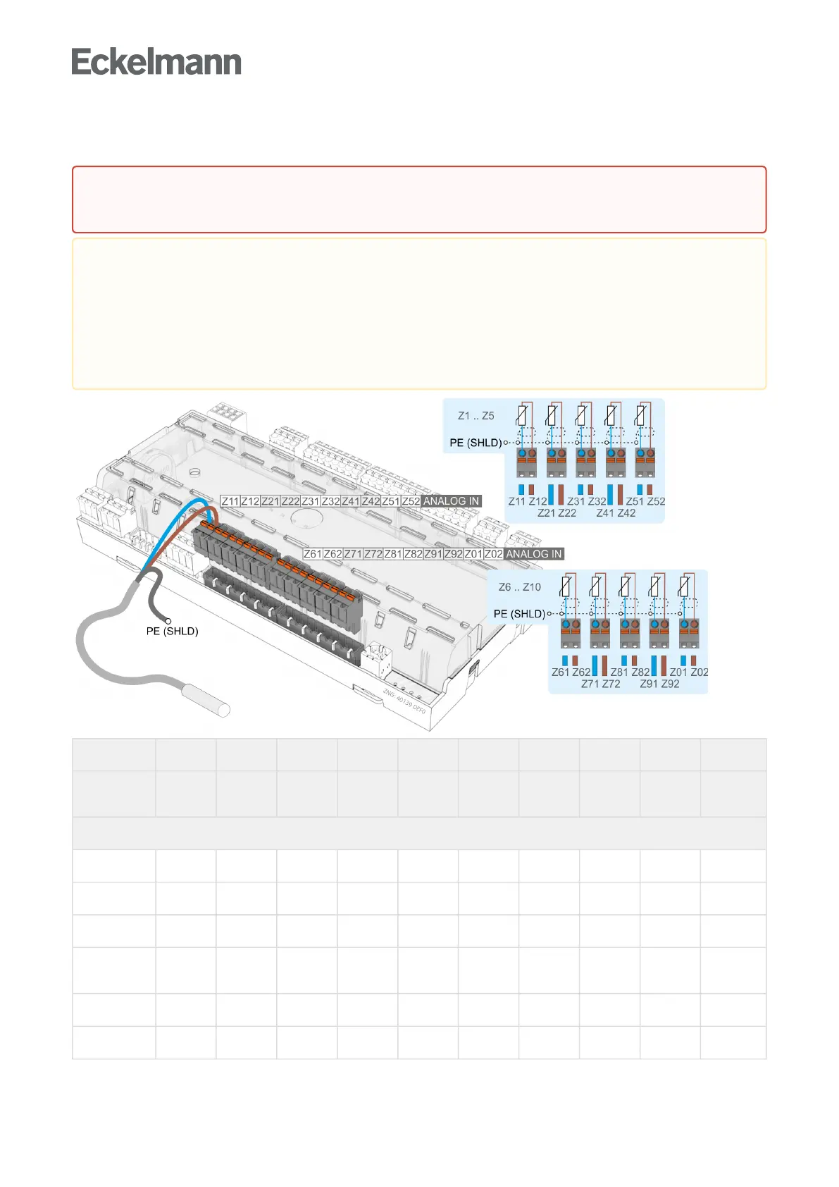
7.11 Terminal assignment of the analogue inputs for temperature sensors
Sensor 1 Sensor 2 Sensor 3 Sensor 4 Sensor 5 Sensor 6 Sensor 7 Sensor 8 Sensor 9 Sensor 10
Controller
type
Z11/Z12 Z21/Z22 Z31/Z32 Z41/Z42 Z51/Z52 Z61/Z62 Z71/Z72 Z81/Z82 Z91/Z92 Z01/Z02
Case controller
UA 111 R2.1 R4.1 R2.2 R4.2 R2.3 R4.3 R2.4 R4.4 – –
UA 111 D R2.1 R4.1 R2.2 R4.2 R2.3 R4.3 R2.4 R4.4 R2.5 R4.5
UA 121 R2.1 R4.1 R1.1 R4.2 R1.2 R2.3 R4.3 R1.3 R4.4 R1.4
UA 131 / UA
131 LS
R2.1 R4.1 R1.1 R4.2 R1.2 R2.3 R4.3 R1.3 R4.4 R1.4
UA 131 DD R2.1 R4.1 R1.1 R4.2 R1.2 R2.3 R4.3 R1.3 R4.4 R1.4
UA 141 R2.1 R4.1 R2.2 R4.2 R2.3 R4.3 R2.4 R4.4 – –
Warning about dangerous electrical voltage!Ifmainspowerisconnectedtotheanalogueinputs,
this results in destruction of the controller!
Malfunction due to interference!Allsupplylinesfromandtothecasecontrollermustbeshielded
(cable type: LiYCY)! If sensor cables are exclusively laid within the refrigerated case to be monitored
and sources of interference (e.g. parallel power lines) are not anticipated, then it is possible to
dispense with shielding. As a general rule, care should be taken to ensure that signal cables and
cables carrying mains voltage are routed in separate cable channels The case controller analogue
inputs are only approved for the connection of temperature sensors as named in chapterAuswahl des
Fühlertyps.