Master / Slave mode
The Master / Slave mode is set using the coding switch 4oftheDIPswitchS3:
ON = Master / Slave mode ON
OFF = Master / Slave mode OFF
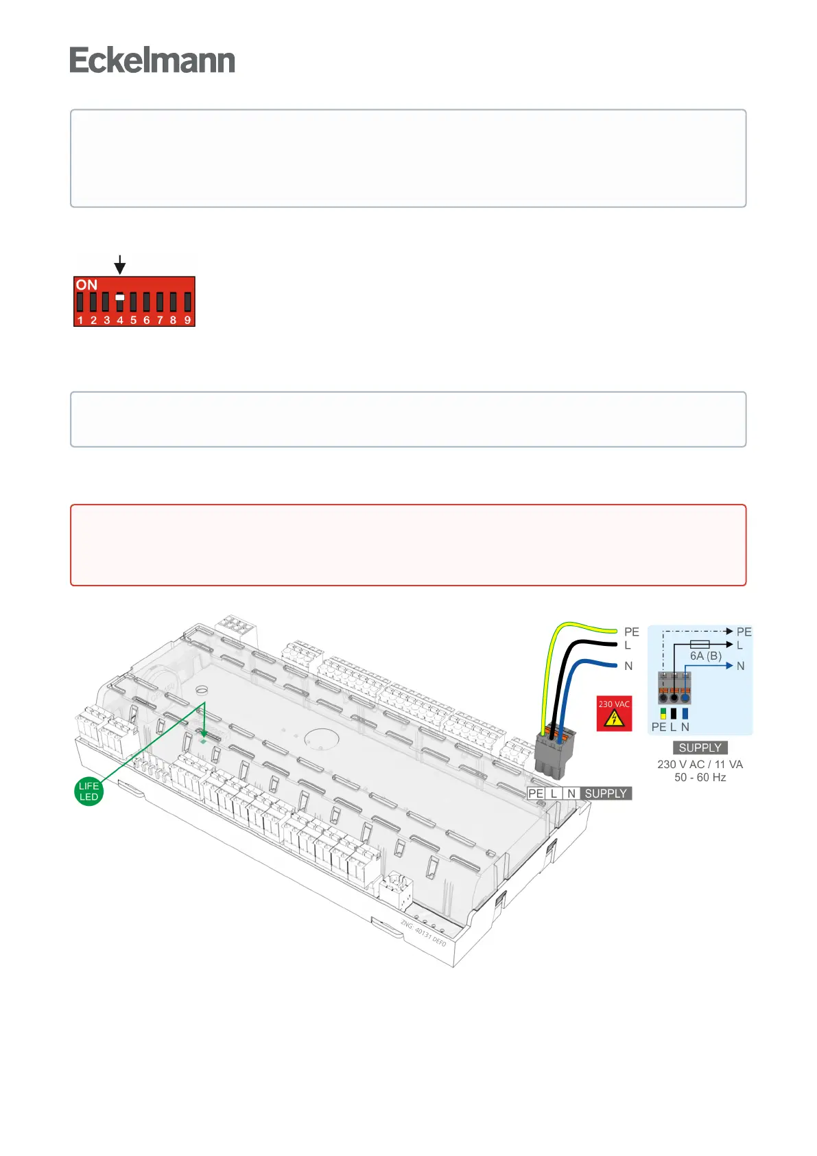
6.3 Terminal assignment for 230 V AC power supply
The power supply cable is connected to the case controller using the right hand terminal block PE/L/N:
The case controller can now be supplied with power. If power is being received the active lamp (LIFE LED)
flashes for approximately 10 seconds following actuation. If the case controller is also connected to the CAN
bus, then the CAN bus LED flashes. For more details on the status LEDs see chapter Status LEDs.
Operation with an unsupported DIP switch setting is not permitted. In the case of any setting of coding
switch combinations that are not present in the list, UA 131 is automatically applied as controller type
and an alarm message is created. In the event of change of the controller type, all parameters are
reset to their factory settings.
ThecasecontrollerdoesnotacceptthechangesontheDIPswitchS3 until after the controller has
been briefly disconnected from the power supply!
Warning - hazardous electrical voltage!
Danger of electric shock! BEFORE andAFTERconnectionitmustcheckedthatthe230VAC
supplycableisoff load!