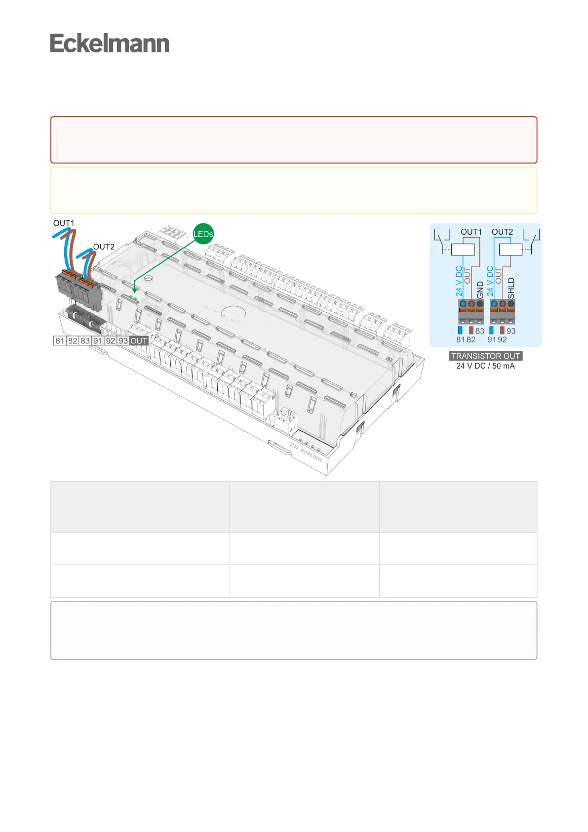
7.8 Terminal assignment of the 24 V DC transistor outputs
Controller type Transistor output 1:
81: 24 V DC / max. 50 mA
82: OUT
83: GND
Transistor output 2:
91: 24 V DC / max. 50 mA
92: OUT
93: SHIELD
UA 111, UA 111 DUA 121, UA 131, UA 131 LS,
UA 131 DDUR 141 NK, UR 141 TK
Lighting control
(terminals 81/82)
Frame heater
(terminals 91/92)
UA 141 Lighting control
(terminals 81/82)
Control of external devices
(terminals 91/92)
Warning about dangerous electrical voltage!
If mains power is connected to the transistor outputs, this results in destruction of the controller!
Destruction of the transistor outputs!Duetothemaximumcapacityof50mAofthetransistor
outputs, 24 V DC coupling relays must be used for controlling the load.
If any transistor output is activated by the controller, the associated green LED lights; for details see
chapter Status LEDs.Forfurtherdetailsaboutthefunctionoftheoutputs,seechapterWirksinn der
Relais- und Transistor-Ausgänge.