7.14 Wiring of the master-slave function for defrost synchronization
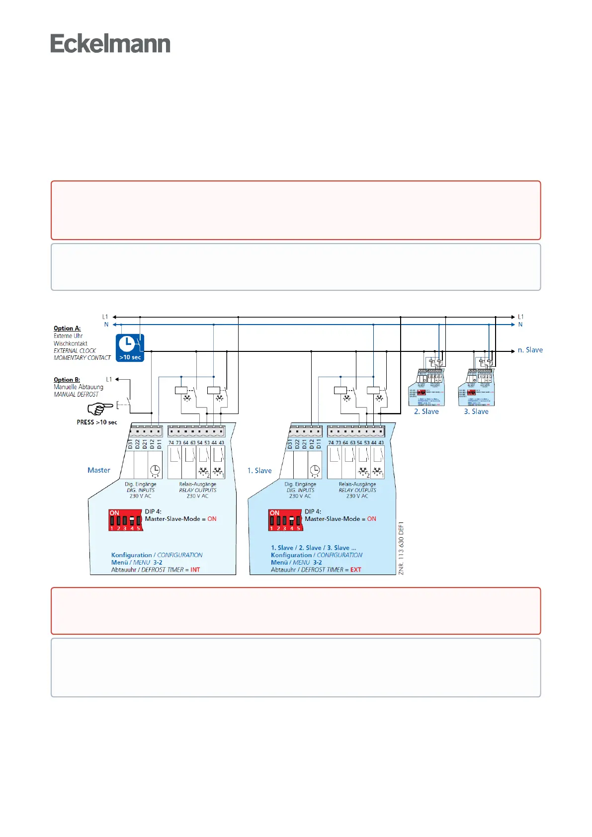
For defrost synchronization via wiring the auxiliary contactors of the master defrost relay are switched in parallel
and then routed as a 230 V signal to the slave's external defrost input (terminals D11/D12). The auxiliary
contactors of the slave controller are also connected in parallel and conducted back as a 230 V level to the
external defrost input of the master. This enables the software to determine whether defrosting is still taking
place in both case controllers.
Basicdiagramforwiringbetweenonemasterandoneormoreslavecase/cold-roomcontrollers:
Warning - hazardous electrical voltage!
Danger of electric shock! BEFORE and AFTERconnectionitmustcheckedthatthe230VACdigital
inputs are off load!
The description and operating instructions for the master-slave mode via wiring are contained
inchapterBrine defrosting.
Danger of short circuit!Whenwiringmasterandslavecase/cold-roomcontrollers,makesurethat
powersupplyismadewithonlyonephase(e.g.onlythroughL1,seeillustration)!
Defrosting is terminated by the software not later than when the set safe defrost time expires. The
external clock must be wired as a passing contact as it only provides the start signal for the defrosting.
The shutdown is entirely managed by the participating controllers according to their safe defrost time.