•
•
•
•
•
•
•
•
•
•
•
•
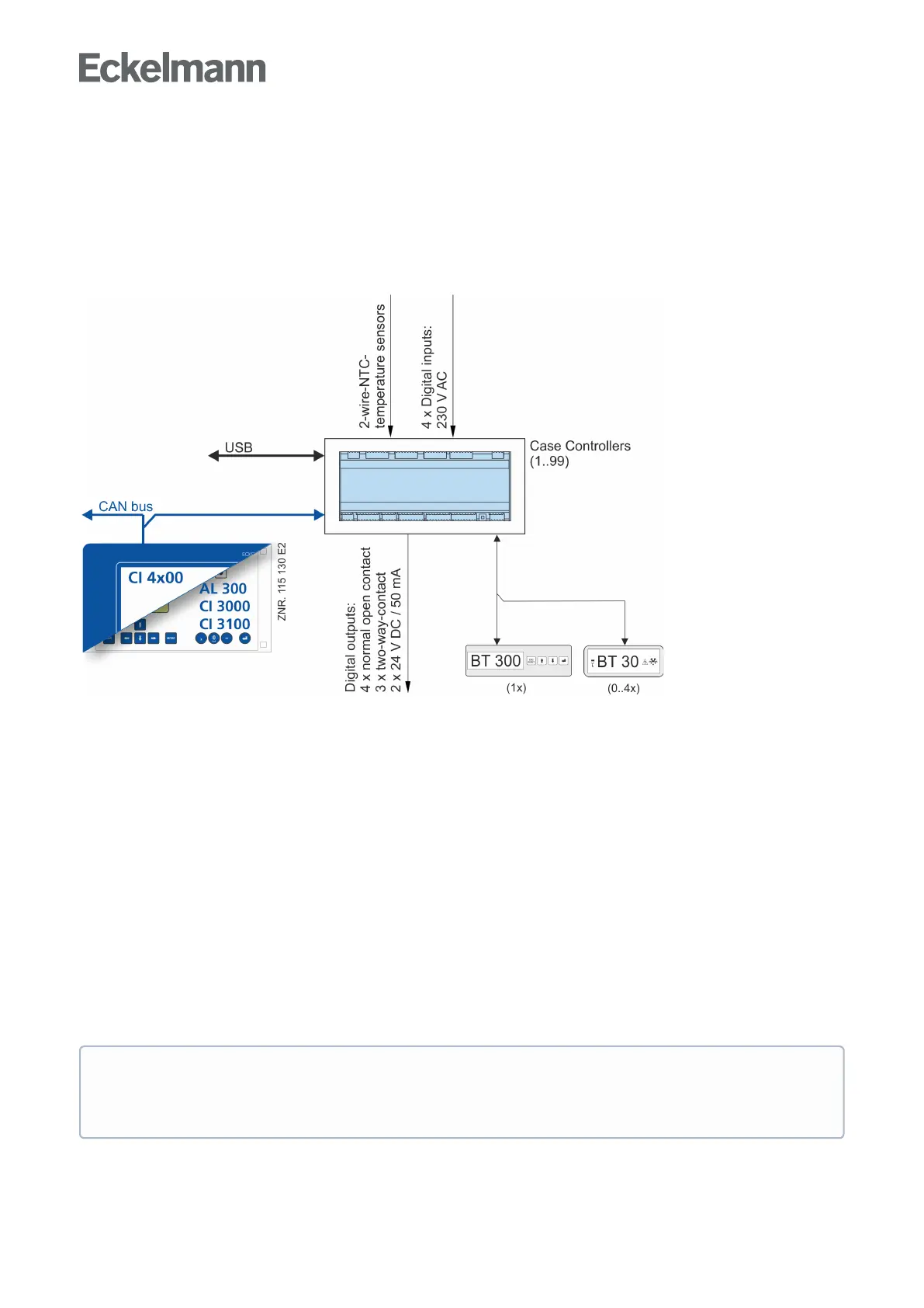
3.2 Hardware
The case controller is housed in a plastic casing for DIN rail mounting and does not require any further optional
expansion modules. Up to 99 case controllers can be used within the LDS system. As required, a BT 300 x
Operator Interface and up to 4 BT 30 Temperature Displays can be connected. For the direct parameterisation
via LDSWin or for a firmware update, the controller can be connected to a laptop or PC via the USB interface.
TheapplicationrangeofthecasecontrollerisdescribedinmoredetailinchapterVersions.
The following diagram illustrates the system architecture of the UA 410 AC case controller (complete):
Ports
CAN bus: Communication in E*LDS-System, new version
DISPLAY: Connection for BT 300x Operator Interface and up to four BT 30 Temperature Displays
CI 320: Communication with LDSWin software / Connection to the legacy system CI 320
USB: For conducting a firmware update
Inputs/outputs
4 digital inputs 230 V AC, floating
10 analog inputs Connection for two-wire NTC temperature sensors
Only UA 410 AC:2 x analogue inputs 4..20 mA - currently without function
Outputs
3 relay output 230 V AC / 6 A (changeover)
4 relay outputs 230 V AC / 6 A (N.O.)
2 transistor outputs 24 V DC / 50 mA (for lighting control and frame heater)
Only UA 410 AC:2 x analogue outputs 0..10 V DC - currently without function
Real-time clock
Only UA 400 AC: Battery-backed, lithium cell
ForprecisedetailsofthedifferentfeaturesofthecontrollersUA400CCandUA400AC
seechapterController types. The connection and terminal configurations are described in
thechapterPin and Terminal Assignments of UA 400.