•
•
•
•
•
•
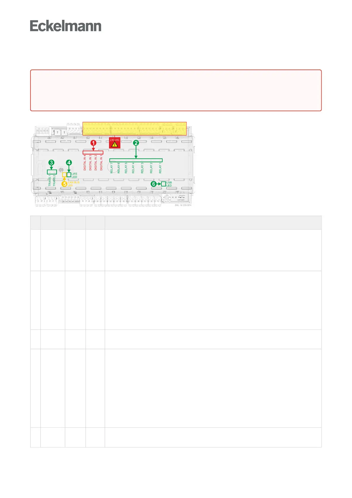
6.3.1 Status LEDs
Function Colour LED Description
1 230 V AC
Digital
inputs
red LED2
LED3
LED4
LED5
ON: Digital input 1 is activated (terminals D11/D12)
ON: Digital input 2 is activated (terminals D21/D22)
ON: Digital input 3 is activated (terminals D31/D32)
ON: Digital input 4 is activated (terminals D41/D42)
ATTENTION: External voltage can be present at these terminals!
2 230 V AC
Relay
outputs
green LED6
LED7
LED8
LED9
LED10
LED11
LED12
ON: Relay 1 is switched (terminals 15/16/18)
ON: Relay 2 is switched (terminals 25/26/28)
ON: Relay 2 is switched (terminals 35/36/38)
ON: Relay 4 is switched (terminals 43/44)
ON: Relay 5 is switched (terminals 53/54)
ON: Relay 6 is switched (terminals 63/64)
ON: Relay 7 is switched (terminals 73/74)
ATTENTION: External voltage can be present at these terminals!
3 Transistor
outputs
green LED13
LED14
ON: Transistor output 1 is switched (terminals 81..83)
ON: Transistor output 2 is switched (terminals 91..93)
4 LIFE green LED15 Controller with 8-pole DIP switch
FLASHING:Activelamp,controllerissuppliedwithpower,processorisrunningorcontroller
is in firmware update mode (all coding switches 1..8 of DIP S3 are ON), for details see
chapter
OFF: Power supply interrupted or device defective Update für Regler mit 8-poligem DIP-
Schalter
Controller with 9-pole DIP switch
FLASHING: Active lamp, controller is supplied with power, processor is running
OFF:Powersupplyinterruptedordevicedefectiveorcontrollerisinfirmwareupdatemode
(coding switch 9 of DIP S3 is ON), for details see chapter Update für Regler mit 9-poligem
DIP-Schalter
5 CAN bus orange LED1
FLASHING: LED always flashes when data are being exchanged via the CAN bus with the
system centre / store computer.
OFF: CAN bus connection interrupted or CAN bus defective
DANGER
Warning about dangerous electrical voltage! Danger of electric shock!Thedevicemustneverbe
operated without its case. Before opening the case, the device must be disconnected from the power
supply.