•
•
•
•
6.2 Basic settings
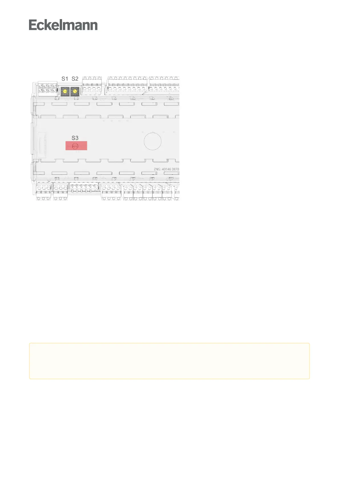
Settings BEFORE the connection of the power supply - S1, S2, S3
Decade switches S1 and S2:
-SettingoftheCANbusaddress(nodenumber)1..99,seechapterSetting the CAN bus address
DIP switch S3:
-Controllertypesetting
-Master/Slavemode
-Settingofspecialfunctions,seechapterSetting of the controller type and master/slave mode
Settings AFTER application of the power supply
Erstanlauf - Regler auf Werkseinstellungen zurücksetzen(optionalsettingtodefaultvaluestoreacha
defined initial state for a running operation)
Configurationofthecontroller,seechapterGrundkonfiguration des Reglers
6.2.1 Setting the CAN bus address
Setting of the CAN bus address (Kn.nnn = 1..99) is performed using the two decade switches S1 and S2. An
individual CAN bus address must first be set at the two decade switches on all case controllers that are
installed in refrigerated cases beforecommissioning.
Risk of confusion!Inordertoavoidmix-ups,itisrecommendedtousethepositionnumberofthe
refrigerated case as CAN bus address. A different CAN bus address that must be unique in this system
must be allocated to each refrigeration point. The CAN bus address is inactive if both decade switches
aresetto0(i.e.theaddressis00).Thecontrollerisnotrecognisedasabusnode.