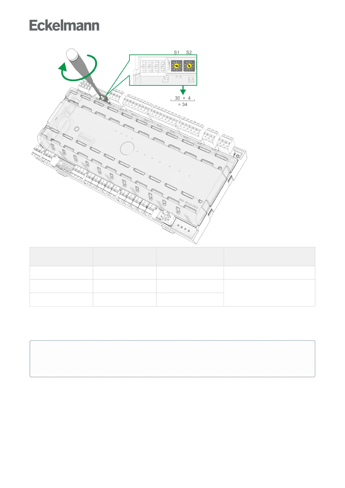
S1
(10 position)
S2
(1 position)
Configured
CAN bus address
Function
0 0 00 CAN bus interface inactive (disabled)
0 1..9 01..09 Case controller: CAN bus address
assigned
1..9 0..9 10..99
Example:
S1 = 3 = 3 x 10 = 30 and
S2 = 4 = 4 x 1 = 4
→CANbusaddress=S1+S2=30+4=34
The case controller does not accept the settings on the decade switches S1andS2 until after the
controller has been briefly disconnected from the power supply! In the case of case controllers that are
installed in a switch cabinet, the CAN bus address has been set by the manufacturer. However, it can
be subsequently adjusted.