•
•
•
•
Menu6-2Controller
CONTROLLER POS: XXXXX
1 Type and Version Move to menu 6-2-1
2 Temp. Display Move to menu 6-2-2
3 Alarm Delay Move to menu 6-2-3
4 230V Inputs Move to menu 6-2-4
5 Sensor Type Move to menu 6-2-5
Menu6-2-1TypeandVersion
VERSION POS: XXXXX Entry Default
Ctrlr. Type XXXXXXX Controller type set by DIP Switch S3 – UA131DD
Software Ver.: XXXX Software version of case/cold-room controller – x.yy
Serial No.: XXXXXX Device No. of case/cold-room controller –
Master/Sl. Mode XXX Synchronized defrosting in master-slave mode
(ON/OFF)
–
Menu6-2-2Temp.Display
DISPLAY POS: XXXXX Entry Default
Offset XX K Offset for temperature display -10..10 0K
Alarm symbol X Show alarm symbol on BT 30 Temperature
Display
, ,(Y/N)
N
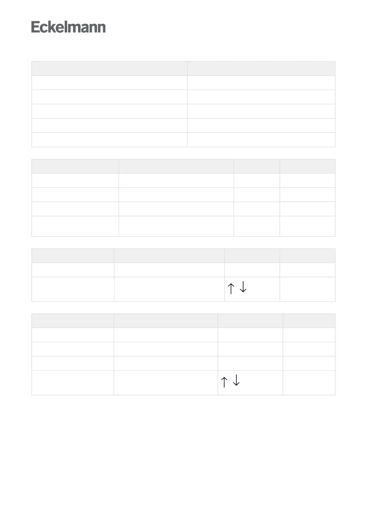
Menu6-2-3AlarmDelay
ALARMDELAY POS: XXXXX Entry Default
Sensor Fault XX m Sensor break alarm delay 0..30 15 min
High/Low Temp. XX m High/low temperature alarm delay 0..150 60 min
No Defrost XX h No defrost alarm delay --, 2..168 50 h
Selfholding X NO: Automatic reset of non- transient alarms.
YES: Alarms must be reset manually.
, ,(Y/N)
N