Operation of VS 300
93
Doku-Version 2.05 - Firmware 2.10 - 15. September 2017
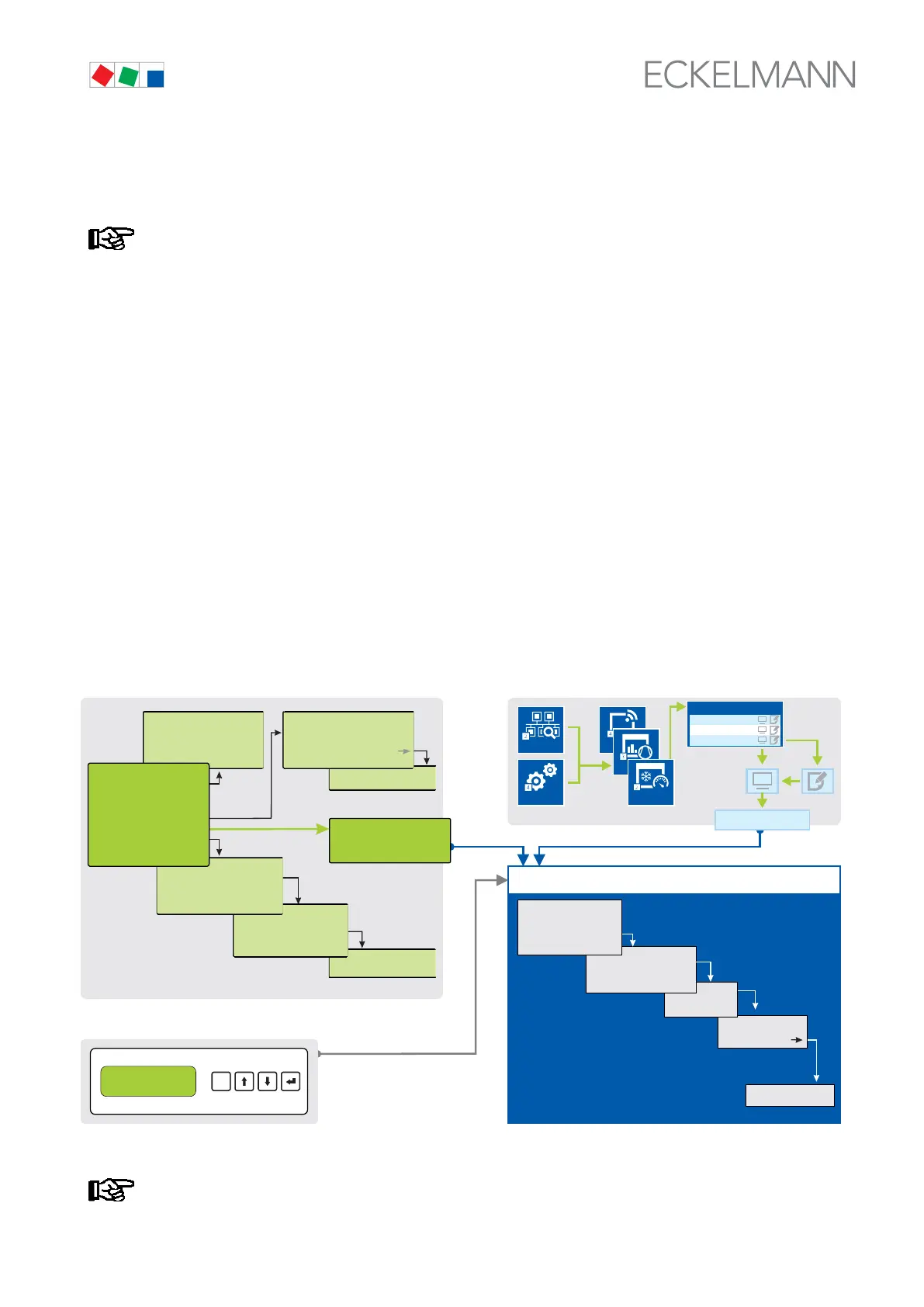
7.16.1 Menus and operating screens
If the system centre, store computer or operator terminal remain locked down, settings on the con
troller are read-only.
Changes and inputs are not possible. However, if any parametrisation is required, the lock-down for
the input must be removed first, see chapter 7.16.3.
Numbering of menus and screens:
Every menu in the menu tree can be reached using a specific number and every operating screen in a menu
can be reached using a specific selection in the menu. This is identified in the operating manual by a unique
identifier of digits (and letters if necessary) in the menu tree (e.g. Menu 3-1-2-a). Thereby, the digits 1, 2, ..
stand for the identification of the corresponding menu, and the letters a, b, .. stand for the sequence of the corre
sponding operating screens in the menu.
Example for the numbering of a menu / screen
Any reference to, for example Menu 3-1-2 in the operating manual means that the required menu of the E*LDS
component is called by entering the digits or selection of "3 - 1 - 2" via the remote control in the system centre,
store computer or operator interface. The menu item "Remote control" is the interface for the E*LDS controller;
see chapter 7.16.2 for details.
If any letter is appended (e.g. Menu 3-1-2-a), this means that another submenu (operating screen or selection
list) can be reached using the cursor right button ( → ). The letters indicate their sequence in the screen.
If any menu or operating screen consists of more lines than are possible in the display, scrolling is possible us
ing the cursor buttons ( ↑ ) and ( ↓ ).
3. Sub menu
CI 3x00 /AL 300
BT 300 x
ESC
RESET
Operator interfaces only for
- UA 300 Family
- UA 400 Family
- WR 300
- WR 400
1 Summary
2 Actual values
3. Sub menu
Menu 3-1-2
2. Sub menu
1 System conf.
2 ...
3 ...
3
E*LDS component
ZNR. 51203 67 930
E4
1. Sub menu
1
Menu 3-1
2
Sub masc
Menu 3-1-2-a
a
CI 4x00
Configuration
Anlagenübersicht
Read
only
Controller
LT Milk
LT Island
NT Room
Service
Remote control
Main menu
1 Summary
2 Actual values
3 Setpoints
4 ...
via
CAN bus
via
CAN bus
via
DISPLAY
interface
REMOTE CONTRL XXX
CONTROLLER NAME
Item ID XXX
Controller menu
Empfangsmodul
Funksensoren
Verbund-
steuerungen
Kühlstellen-
regler
1. sub menu
Main menu
1
5
6
4
Main menu
1
1
1 Alarms
2 Overview
3 Archive
4 Messages
5 Remote Control
6 Store Computer
7 ...
ALARM XXX
CONTROLLER NAME
Item ID XXX
...
MSG/ALARM xxx
CONTROLLER NAME
Item ID XXX
Input screen
2
Menu 6-1-2
1 Expansion Stage
2 Alarm Inputs
3 ...
2. Sub menu
REMOTE CONTRL XXX
CONTROLLER NAME
Item ID XXX
1. Sub menu
In contrast to the system centre, store computer or operator terminal,
the menu of the controller is displayed directly on the operator interface.