Operation of VS 300
79
Doku-Version 2.05 - Firmware 2.10 - 15. September 2017
7 Operation of VS 300
7.1 Integral display, indicators and controls
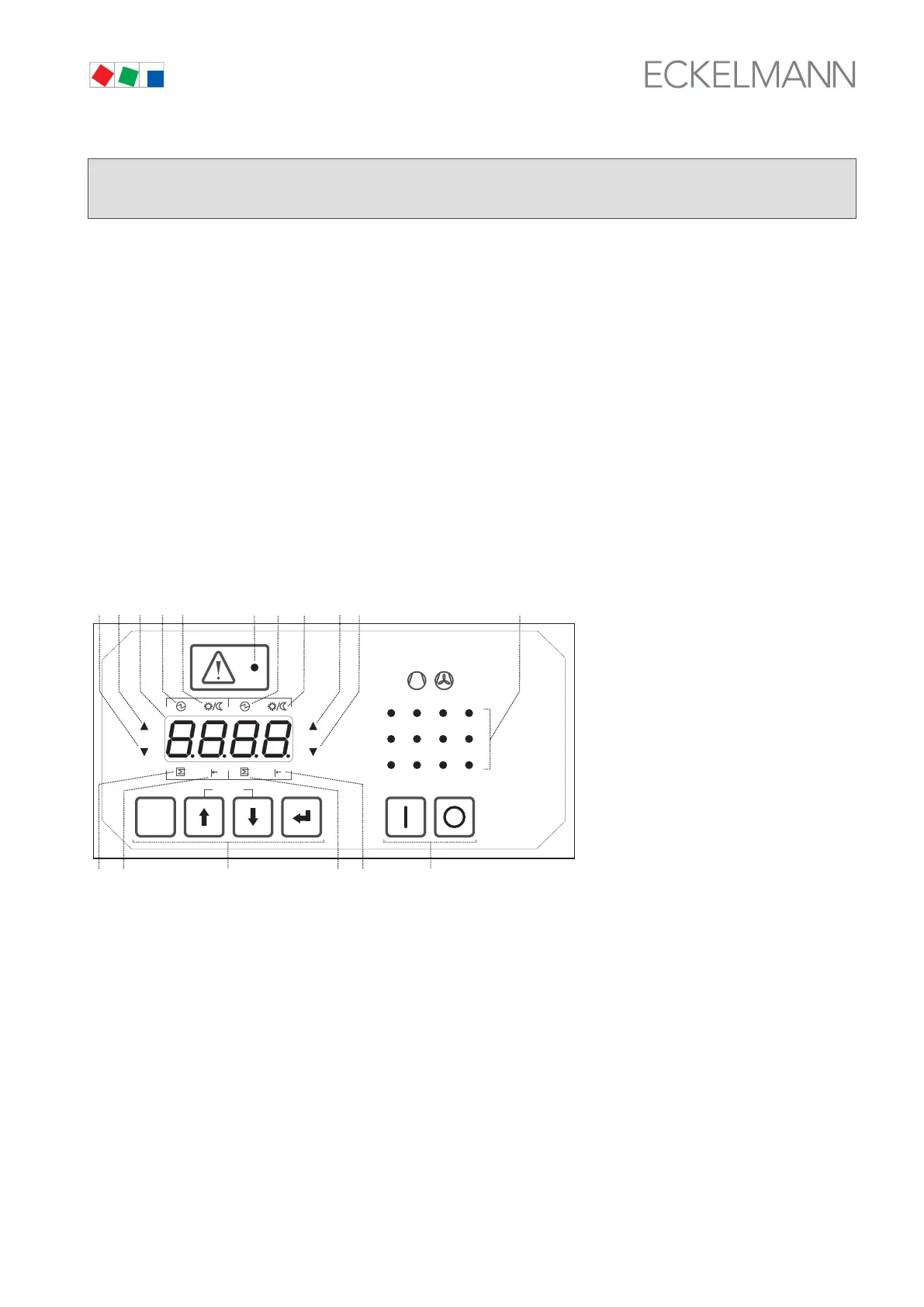
The front panel of the VS 300 Pack Controller contains a four-digit seven-segment LED display, a number of
status LEDs and an alarm/message LED (see illustration). Depending on the operating level, the display and
LEDs show actual values and setpoints, parameter numbers or alarms and messages.
Four keys on the VS 300 can be used for local configuring, parameter setting and operation by means of param
eters described in detail in section 7 Parameter List and Menu Structure. A separate switch on the right of the
control panel is used to control external devices.
7.1.1 Display and LEDs
ESC
RESET
1 2 3 4
1 2
5 6 8
9 10 11 12
7
Status
12
OFF
ZNR. 51203 50
730
OFF
(4)
(1)
(2)
(16)(17)
(8)
(10)
(9)(11) (3)
(12) (14) (13)
(15)
(5)
(6)
(7)
(1) Four-digit seven-segment LED display to show actual values/setpoints, parameter numbers during con-
figuration and parameter setting, compressor/condenser numbers and alarms/messages.
(2) Alarm/message LED (red).
(3) Twelve green LEDs as operating and status indicators for relay/control stages (one per stage).
Depending on the expansion stage 4, 8 or 12 relay/control stages are available for compressor/conden-
ser control (see section 1 Design). Depending on the operating level, all of these LEDs are used to
support entry of values or choices during parameter setting (e.g. indicating the associate compressor or
condenser).