Function of VS 300
19
Doku-Version 2.05 - Firmware 2.10 - 15. September 2017
4.2 Configuration / monitoring of digital inputs
External alarms and messages can be transmitted to the VS 300 through four freely configurable digital inputs.
These inputs can also be used to activate the following operating modes on the VS 300:
S Fast unload:
All control stages are unloaded in rapid sequence in the respective control loop. Die Verbraucherfreigabe der
zugehörigen Kühlstellenregler wird entzogen, es sei denn, der Niderdruck ist zu tief.
S Load shedding:
A definable number of control stages is disabled in the respective control loop.
S Second setpoint:
Setpoint toggle is performed in the respective control loop by an external signal (e.g. central lighting).
S External alarm:
An external signal (e.g. motor overload cutout, etc.) can be detected as an alarm by the VS 300 and reported.
When the CAN bus module is installed, the alarm message can display a user-definable text.
S Heat recovery mode (HR mode):
By activating HR mode, the respective HP control loop can be made to work at higher HP control loop conden
sing temperature.
S Safety loop:
All control stages are unloaded immediately in the respective control loop! A message is transmitted. When
the CAN bus expansion is installed, this message can display a freely definable text. Die Verbraucherfreigabe
der zugehörigen Kühlstellenregler wird entzogen, es sei denn, der Niderdruck ist zu tief.
The following parameters can be set for these four digital inputs (see section 7 Parameter List and Menu Struc
ture – Common Setpoints - System Configuration).
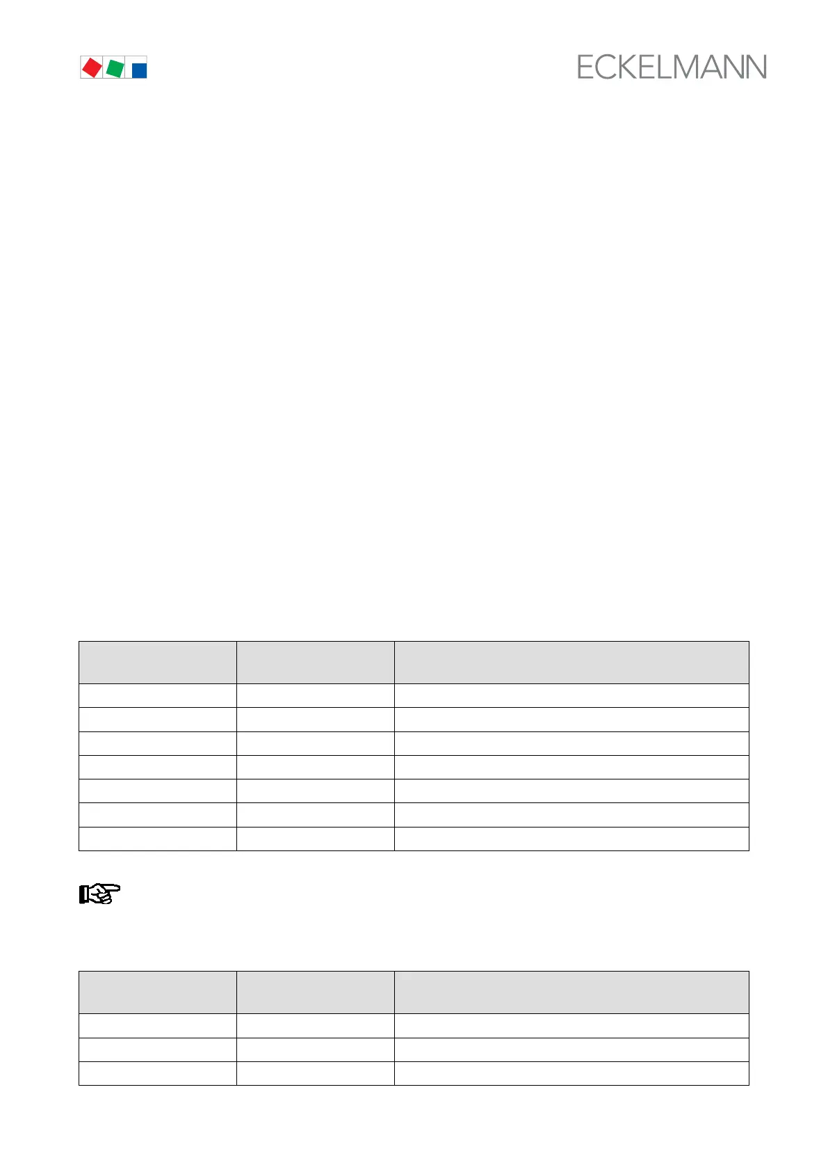
A - Function of digital input:
Integral operation
VS 300 LED display
Display
AL 300 or CI 3000
Function
0 OFF Deactivated
1 FastRet. Fast unload CL 1/2
2 Load Shed Load shedding CL 1/2
3 SetpTog. Second setpoint toggle CL 1/2
4 Ext.Alarm External alarm (no CL assignment)
5 HR Heat recovery mode CL 1/2
6 SaftyL. Safety loop CL 1/2
Ext. Alarm is independent of the control loop and a user-definable text can be entered.
B - Assignment of digital input to control loop (defines which control loop the selected function acts on):
Integral operation
VS 300 LED display
Display
AL 300 or CI 3000
Assignment
0 CL1 Assigned to Control Loop 1
1 CL2 Assigned to Control Loop 2
2 All Assigned to both control loops