Startup of VS 300
62
Doku-Version 2.05 - Firmware 2.10 - 15. September 2017
5.2 Installation
The VS 300 is housed in a plastic casing designed for control panel mounting. Power loss of the controller is
approx. 10 VA. When installing, make sure that the ventilation slots on the controller are not covered and that
sufficient clearance is maintained between devices or cable ducts above and below the controller for cooling air
to circulate.
See section 9 Specifications for details of electrical enclosure, measurements and installation cutout.
See section 5 for pin and terminal assignments.
Attaching mounting braces and installation
The two mounting braces enclosed with the VS 300 must be attached on the left and right sides of the casing for
installation:
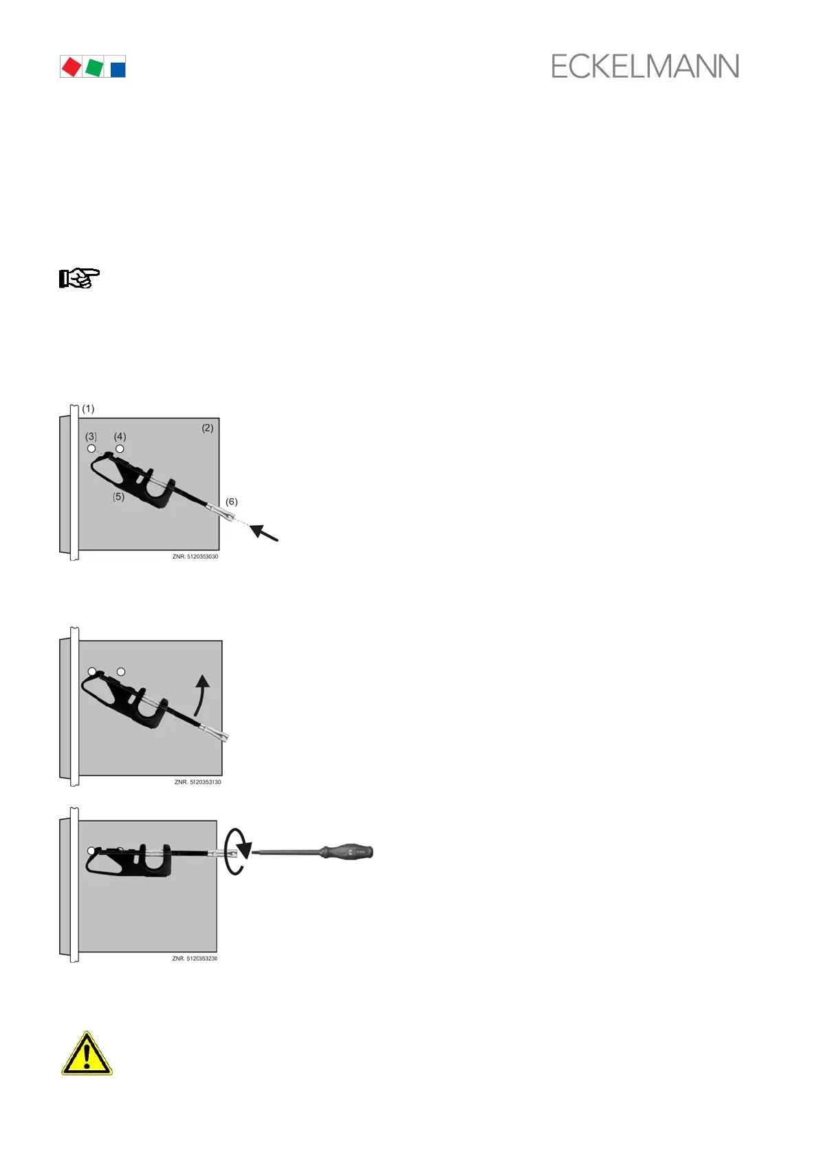
(1) Control panel with installation cutout
(see section 9 Specifications)
(2) Casing of VS 300
(3) Front support pin
(4) Rear support pin
(5) Fastening brace
(6) Fastening brace
1. Push front of VS 300 (2) through cutout in control panel (1). Press fastening brace (5) on front
support pin (3).
2. Turn fastening brace (5) up on front support pin (3) and press
slightly to snap on second support pin (4).
3. Usingg a screwdriver, tighten fastening
screw (6) on control panel.
Then make electrical connections on
VS 300 (see section 5).
After completing installation and electrical connections, parameter settings must be made on the hardware and
in the software of the pack controller.
All leads running to and from the VS 300 – especially those for the analog inputs (sensor leads) and
also for the CAN bus - must be screened!