Function of VS 300
53
Doku-Version 2.05 - Firmware 2.10 - 15. September 2017
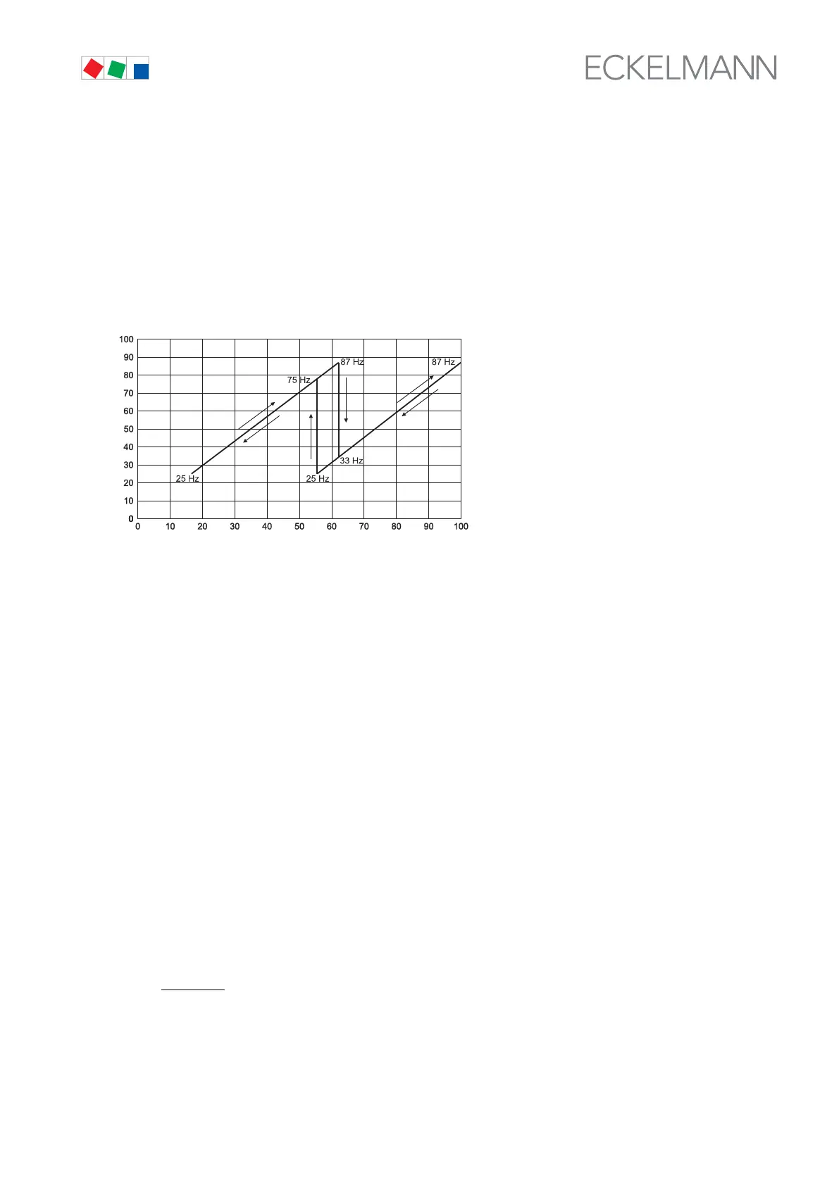
4.5.8 Loading and unloading of fixed-speed fans
Fixed-speed fans can be loaded or unloaded if the required capacity cannot be supplied by changing the fan
speed. When the variable-speed fan attains maximum speed, the next fixed-speed fan is started. When the vari
able-speed fan attains minimum speed, a fixed-speed fan is stopped.
The variable-speed fan is increased to a speed at which the condenser capacity corresponds to the capacity
prior to stopping the fixed-speed fan. The speed controlled fan is powered up again. The control sequence for a
condensing unit equipped with two fans is shown in the following diagram.
Condensor with capacity control
Frequency of speed
-controlled
condensor
[
Hz]
Relative refrigeration capacity of condensor [%]
ZNR. 51203
63 130 E0
4.5.9 Condenser fan actuating times with step action controller
If condensing pressure rises above or drops below the neutral zone, the first condenser capacity stage is imme
diately loaded or unloaded. Further actuation only occurs when a certain time for loading or unloading has
elapsed and the control error exceeds a defined value (neutral zone).
If the control error is positive and greater than half the neutral zone but pressure is falling, no fan actuation takes
place, as it may be anticipated that pressure will soon come within the neutral zone. Conversely, no fan actua
tion takes place when the control error is negative and greater than half the neutral zone but pressure is rising,
as it may again be anticipated that pressure will soon come within the neutral zone.
Actuating time is a function of the actual control error. With a large control error, actuation takes place sooner
than with a smaller control error. The actuating time is calculated as the total of basic time t
b
and variable time
t
v
. On step controllers differentiation is made between loading and unloading.
The variable time is inversely proportional to the control error. At maximum control error the variable time t
v
de
creases to 0. As the control error becomes smaller, time t
v
is automatically increased up to the defined maxi
mum. Basic time and maximum variable time for loading and unloading are programmable parameters. The fol
lowing relationships apply to calculating actuating times:
t = t
b
+ t
v
t
b
definable
The following applies for t
v
:
t
v
t
v_max
t
v_max
d
t
d
t_max