Function of VS 300
17
Doku-Version 2.05 - Firmware 2.10 - 15. September 2017
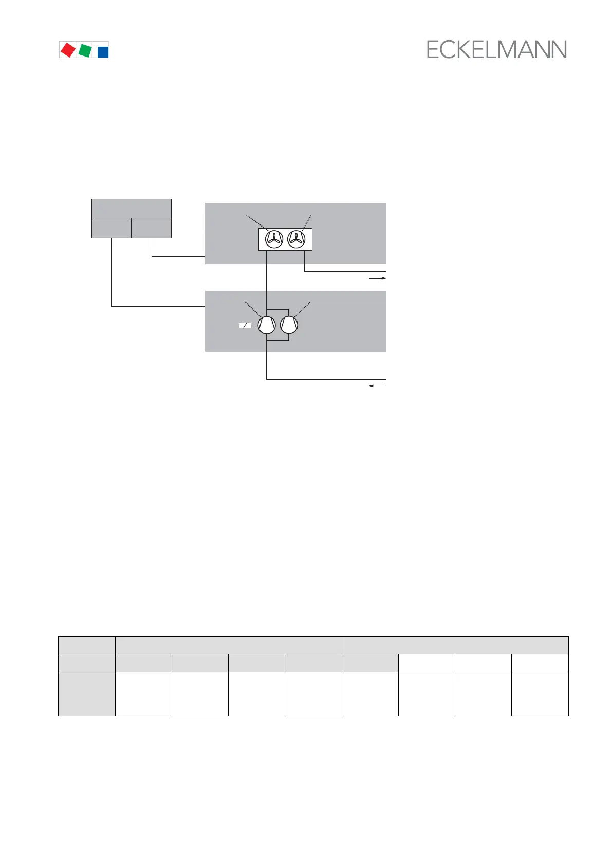
4.1.3 Example of VS 300 system configuration
System requirements: - VS 300 without CAN bus module
- 2 fans
- 2 compressors (1 capacity-controlled and 1 single-stage compressor)
HP
ZNR. 51203 51 730 E1
LP
to NT/LT ref. point
VS 300
CL2CL1
Controlloop 2
Controlloop 1
from NT/LT ref. point
1CL
G=2
AL = 2
CL2
GS1
CL2
GS2
1CL
LS1
CL1
GS2
CL1
GS1
1CL
L = 2
1CL
B = 1
2CL
G=2
2CL
L = 1
2CL
B = 0
Calculation of relay/control stages required for system configuration in example:
G
CL1
= 2, L
CL1
=2, B
CL1
=1 G
CL2
=2, L
CL2
=1, B
CL2
=0
G
CL1/2
= Total number of base load stages, Control Loop 1/2
(compressors with and without capacity control)
L
CL1/2
= Number of capacity stages each capacity-controlled base load stage, Control Loop 1/2
(= 1 for compressors without capacity control)
B
CL1/2
= Number of capacity-controlled base load stages, Control Loop 1/2
AL = Number internal alarm relais
Result:
=> Number of relay/control stages required for this VS 300 configuration:
=> VS 300 with first expansion stage is necessary to implement this configuration
VS 300 Basic configuration First expansion stage
Relay No. S1 S2 S3 S4 S5 S6 S7 S8
Terminals
Numbers
Each relay
35
36
38
45
46
48
55
56
58
65
66
68
75
76
78
85
86
88
95
96
98
105
106
108
G
CL1/2
= Basic load stage of standard or capacity-controlled
- compressor with LP control (CL1)
- Motor of fan with HP control (CL2)
LS
CL1/2
= Capacity stage of capacity-controlled compressor (Bypass valve, etc.)
n.c. = Not connected/assigned